Chapter 1
Introduction
Chapter 1: Introduction
1-1
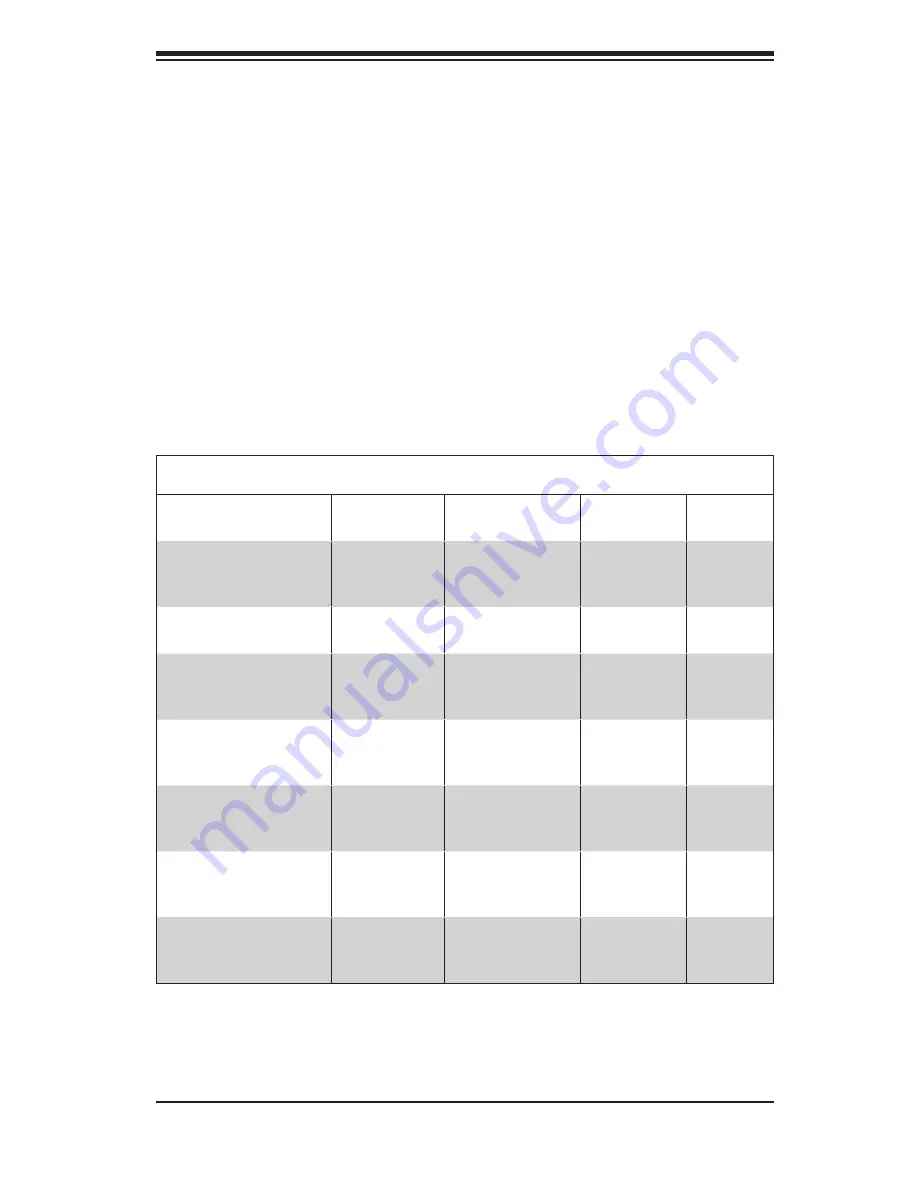
SC825 Chassis
Model
CPU
HDD
I/O Slots
Power
Supply
SC825TQ-R700LP
DP Dual-core
Xeon
8x SAS / SATA
w/SES2
7x LP
700W
Redun-
dant
SC825TQ-560LP
DP Dual-core
Xeon
8x SAS / SATA
w/SES2
7x LP
560W
SC825S1-R700LP
DP Dual-core
Xeon
8x Single-Chan-
nel (4 + 4)
SCA w/SAF-TE
7x LP
700W
Redun-
dant
SC825S2-R700LPV
DP Dual-core
Xeon
8x Dual-Channel
(4 + 4)
SCA w/SAF-TE
7x LP
700W
Redun-
dant
SC825S2-560LP
DP Dual-core
Xeon
8x Dual-Channel
(4 + 4)
SCA w/SAF-TE
7x LP
560W
SC825TQ-R700RC2/
R700RC (OEM)
DP Dual-core
Xeon
8x SAS / SATA
w/SES2
3 FF + 3 LP/
3 FF
700W
Redun-
dant
SC825S2-R700RC2/
R700RC (OEM)
DP Dual-core
Xeon
8x Dual-Channel
(4 + 4)
SCA w/SAF-TE
3 FF + 3 LP/
3 FF
700W
Redun-
dant
1-1 Overview
Supermicro’s SC825 2U chassis features a unique and highly-optimized design.
The chassis is equipped with high efficiency power supply.
1-2 Shipping List
Please visit the following link for the latest shipping lists and part numbers for
your particular chassis model http://www.supermicro.com/products/chassis/1U/
?chs=825