background image

Chapter 6: BIOS

119

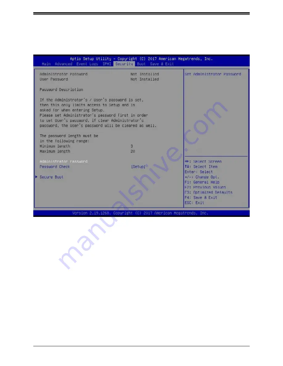
6.7 Security Settings

This menu allows the user to configure the following security settings for the system.

Administrator Password

Use this feature to set the administrator password which is required to enter the BIOS setup 
utility. The length of the password should be from 3 characters to 20 characters long.

User Password

Use this feature to set the user password which is required to enter the BIOS setup utility. 
The length of the password should be from 3 characters to 20 characters long.

Password Check

Select Setup for the system to check for a password at Setup. Select Always for the system 
to check for a password at bootup or upon entering the BIOS Setup utility. The options are 

Setup 

and Always.

Summary of Contents for FatTwin F629P3-RC0B

Page 1: ...USER S MANUAL Revision 1 0 FatTwin F629P3 RTB F629P3 RTBN F629P3 RC0B F629P3 RC1B...

Page 2: ...operated in a commercial environment This equipment generates uses and can radiate radio frequency energy and if not installed and used in accordance with the manufacturer s instruction manual may ca...

Page 3: ...o download all necessary drivers utilities and the user s manual for your server Supermicro product manuals http www supermicro com support manuals Product drivers and utilities ftp ftp supermicro com...

Page 4: ...rboard Layout 15 Quick Reference Table 16 Chapter 2 Server Installation 2 1 Overview 18 2 2 Preparing for Setup 18 Choosing a Setup Location 18 Rack Precautions 19 Server Precautions 19 Rack Mounting...

Page 5: ...r Hard Drive Cage Backplane 37 Installing the Serverboard 38 Compatible Motherboards 38 Permanent and Optional Standoffs 38 Power Adapter Card Replacement 40 Installing Expansion Cards 41 F424AS2 PCI...

Page 6: ...ttery 62 Chapter 4 Motherboard Connections 4 1 Power Connections 63 4 2 Headers and Connectors 63 4 3 Rear I O Ports 65 Ethernet Ports 66 4 4 Front Control Panel 67 4 5 Jumpers 70 Explanation of Jumpe...

Page 7: ...6 7 Security Settings 119 6 8 Boot Settings 122 6 9 Save Exit 124 Appendix A BIOS Error Codes Appendix B Standardized Warning Statements for AC Systems Appendix C System Specifications Appendix D UEFI...

Page 8: ...Sterrenbeeld 28 5215 ML s Hertogenbosch The Netherlands Tel 31 0 73 6400390 Fax 31 0 73 6416525 Email sales supermicro nl General Information support supermicro nl Technical Support rma supermicro nl...

Page 9: ...3 RTB only CBL SAST 1004 1 4 Internal RA reverse Mini SAS HD to 2x Mini SAS HD Y splitter 15 59 cm 30AWG cables F629P3 RC0B F629P3 RC1B only CBL SAST 0691 4 Internal RA reverse Mini SAS HD to Mini SAS...

Page 10: ...d from the chassis The nodes are connected to the server backplane by means of an adapter card Note A guide pin is located between the upper and lower nodes on the inner chassis wall This guide pin al...

Page 11: ...p to 1536 GB of ECC Load Reduced DIMM LRDIMM Registered DIMM RDIMM and Non Volatile DIMM NV DIMM DDR4 288 pin 2666 2400 2133 Mhz modules in twelve 12 slots Chipset Intel C621 chipset Expansion Slots O...

Page 12: ...dicates network activity on either LAN1 or LAN2 when flashing 3 Information LED See the table below for full details on the Information LED 4 UID LED When used with a UID compatible serverboard the UI...

Page 13: ...erver nodes See the illustration below for the features included on the front of the chassis Information LED Status Description Continuously on and red An overheat condition has occurred This may be c...

Page 14: ...ule Bay Each node has one rear SIOM module bay available for additional I O ports 4 Rear Drive Bays Each node has two 2 bays in the rear for 3 5 HDD SSD NVMe drives The configuration of each drive dep...

Page 15: ...VME4 JTPM1 I SATA4 7 3 0 CPU2 PCI E 3 0 X8 I SATA0 3 CPU1 PCI E 3 0 X16 CPU1 PCI E 3 0 X8 PCH BIOS BMC JPP1 JTAG SCAN JPP0 JTAG SCAN CPU2 PCI E 3 0 X16 VGA P1 DIMMC1 COM1 CPU1 USB0 1 DESIGNED IN USA X...

Page 16: ...Power Connector 9 12V_in Power Connector 10 Ground JPWR_HDD1 2 3 HDD Power headers 1 2 3 JRK1 RAID Key for NVMe devices JS1 2 MiniSAS HD SATA 3 0 Ports JSDCARD1 Micro SD Card slot JTPM1 Trusted Platfo...

Page 17: ...M1 Connector VGA CONN BMC Boot Flash DDR4 5 1 PHASE 165W 2133 2666 2133 2666 DDRIV P1 P1 P0 VR13 P0 DDRIV D1 UPI PCI E X16 DMI3 JSXB2 PCI E X8 A1 PCI E X16 2 IM D 2 IM D UPI 10 4 11 2G 5 1 PHASE 165W...

Page 18: ...shipped should include the rackmount hardware needed to install it into the rack Please read this section in its entirety before you begin the installation Choosing a Setup Location The system should...

Page 19: ...r components at the bottom of the rack first and then work your way up Use a regulating uninterruptible power supply UPS to protect the server from power surges and voltage spikes and to keep your sys...

Page 20: ...all times To ensure this the rack itself should be grounded Particular attention should be given to power supply connections other than the direct connections to the branch circuit i e the use of powe...

Page 21: ...it Warning Do not pick up the server with the front handles They are designed to pull the system from a rack only Stability Hazard The rack stabilizing mechanism must be in place or the rack must be b...

Page 22: ...two rail assemblies in the rack mounting kit Each assembly consists of two sections A front section which secures to the front post of the rack and a rear section which adjusts in length and secures t...

Page 23: ...outer rail with the slots on the front post of the rack Secure the front of the outer rail to the rack with two screws 3 Pull out the rear section of the outer rail adjusting the length until it fits...

Page 24: ...ver from coming completely out of the rack when pulled out for servicing Note The figure above is for illustration purposes only Always install servers to the bottom of the rack first Figure 2 3 Insta...

Page 25: ...h section 3 1 Removing Power Use the following procedure to ensure that power has been removed from the system This step is necessary when removing or installing non hot swap components or when replac...

Page 26: ...odes may be removed from the chassis Note that any time a node is removed from the chassis the hard drives located in the node will shut down Removing a Serverboard Node 1 Power down the system and re...

Page 27: ...and to prevent overheating Removing the Cover from the Node Each node has a removable cover which will permit access to the nodes components Removing the Node Cover 1 Remove the serverboard node compl...

Page 28: ...ations for the F424AS2 nodes are shown in the table below F424AS2 Node Layout Specifications Front of Node Rear of Node Six 6 3 5 hot swappable hard drives One SIOM Module One low profile expansion ca...

Page 29: ...the rear Note that if a node is pulled out of the chassis the hard drives associated with that node will power down as well Refer to the table below and on the following pages for your specific chass...

Page 30: ...Removing 3 5 Hard Drive Carriers from the Node 1 Press the release button on the drive carrier This extends the drive bay handle 2 Use the handle to pull the drive carrier out of the chassis The 3 5 h...

Page 31: ...FatTwin F629P3 RTB RTBN RC0B RC1B User s Manual 31 Figure 3 6 Removing a Rear Mounted 3 5 Hard Drive Carrier 1 2...

Page 32: ...oving the Rear Hard Drive Cage Removing the Rear Hard Drive Cage 1 Remove the four screws securing the Rear Hard Drive Cage from the Node Chassis 2 Lift the Rear Hard Drive Cage from the node chassis...

Page 33: ...dummy drive to the drive carrier 3 Lift the dummy drive from the drive carrier Caution Enterprise level hard disk drives are recommended for use in Supermicro chas sis and servers For information on r...

Page 34: ...ard drive 4 Use the open handle of the drive carrier to insert the drive carrier into the open drive bay 5 Secure the drive carrier into the drive bay by closing the drive carrier handle Note that if...

Page 35: ...the handles on the front of the serverboard node pull the node completely out of the chassis and place it on a flat surface 2 Remove the node cover see the section Removing the Node Cover for details...

Page 36: ...of the hard drive carriers have been removed from the bays in the front of the node see the section Installing and Removing Hard Drives for details 2 Ease the backplane forward against the front of t...

Page 37: ...Drive Cage Backplane 1 Remove the two screws securing the Rear Hard Drive Cage Backplane to the Rear Hard Drive Cage 2 Lift the backplane off of the Rear Hard Drive Cage 1 2 1 Figure 3 12 Removing th...

Page 38: ...iguration of the serverboard being used it is also possible that some of the optional standoffs which are pre installed in the chassis may need to be removed Add or remove standoffs as needed Installi...

Page 39: ...s needed The fans may be temporarily removed to allow access to the backplane ports 8 Replace the expansion card bracket and secure the bracket with a screw 9 Repeat steps 3 5 for the remaining nodes...

Page 40: ...wer Adapter Card 1 Remove the node from the chassis and place the node on a flat stable surface Then remove the cover from the node 2 Remove the four screws securing the power adapter card to the moun...

Page 41: ...ne or more expansion cards in each node Refer to the tables below to determine the PCI E slot configuration for your particular chassis F424AS2 Front of Node Rear of Node Six 3 5 hot swappable hard dr...

Page 42: ...e the one screw securing the PCI E Slot Shield 2 Make sure the expansion card is low profile Plug the expansion card into the PCI E slot on the serverboard 3 Secure the expansion card into the rear wi...

Page 43: ...cted To install a module use the procedure below Installing a SIOM module 1 Remove the SIOM bracket by unscrewing two screws one on the side of the node tray one underneath 2 Remove one screw securing...

Page 44: ...the chassis and remove the cover from the node 2 Make sure that the serverboard and all components are properly installed in each node 3 Place the air shroud over the serverboard as illustrated below...

Page 45: ...nd out of the node 3 Disconnect all fan cables from the motherboard 4 Remove the screws securing the fan housing to the floor of the node and set them aside for later use 5 Lift the fan housing up and...

Page 46: ...46 Chapter 3 Maintenance and Component Installation Figure 3 19 Removing the Fan Tray Figure 3 20 Removing the Fan from the Fan Tray...

Page 47: ...2 chassis utilizes two redundant power supplies four in total In the unlikely event that the power supply unit needs to be replaced one power supply can be removed without powering down the system Rep...

Page 48: ...48 Chapter 3 Maintenance and Component Installation Figure 3 21 Changing the F424AS2 Chassis Power Supplies Release Tab...

Page 49: ...all the processor into the CPU socket before you install the CPU heatsink If you buy a CPU separately make sure that you use an Intel certified multi directional heatsink only Make sure to install the...

Page 50: ...ns 1 the Intel Xeon 81xx 61xx 51xx 41xx 31xx series processor 2 CPU heatsink carrier 3 dust cover and 4 CPU socket 3 Dust Cover 4 CPU Socket 1 The Intel Xeon 81xx 61xx 51xx 41xx 31xx series Processor...

Page 51: ...sink Module The processor heatsink module PHM contains 1 a passive heatsink 2 a CPU heatsink carrier and 3 The Intel Xeon 81xx 61xx 51xx 41xx 31xx series processor 1 Passive Heatsink 2 CPU Heatsink Ca...

Page 52: ...GA3647 socket and 4 a back plate These components are pre installed on the motherboard before shipping Processor Socket Assembly W A R N I N G Socket Cover LGA3647 Socket Socket Pins Removing the Dust...

Page 53: ...Align Pin 1 Notch A Notch B and Notch C on the CPU with the corresponding notches on the carrier Once they are aligned carefully insert the CPU into the carrier until you hear a click Once the CPU is...

Page 54: ...ave made a CPU carrier assembly please follow the steps below to mount the assembly onto the heatsink to create the Processor Heatsink Module PHM 1 Place the heatsink upside down with the thermal grea...

Page 55: ...it through the corresponding mounting holes on the socket The PHM will only fit one way If it does not fit correctly remove it and try again 3 Using a T30 size star driver bit tighten four screws into...

Page 56: ...HM counterclockwise to loosen it from the socket starting with screw marked 4 in the sequence of 4 3 2 1 2 After all four screws are removed wiggle the PHM gently and pull up to remove it from the soc...

Page 57: ...ort for the Intel Xeon 81xx 61xx 51xx 41xx 31xx Series Processors Type Ranks Per DIMM and Data Width DIMM Capacity GB Speed MT s Voltage V Slots per Channel SPC and DIMMs per Channel DPC 1 Slot per Ch...

Page 58: ...t in the slot furthest away from CPU Always populate DIMMs with a higher electrical loading in DIMM0 followed by DIMM1 DDR4 Only Memory Populations with Possible Mixes DDR4 RDIMM DIMM0 DIMM1 Config Se...

Page 59: ...DIMM DDR1 Populate identically as DDR0 DDR2 Populate identically as DDR1 1 N A 1 SVLS 4 x8 DIMMs DDR0 Populate with 2 DIMMs DDR1 Populate identically as DDR0 x SVLS 5 x8 DIMMs DDR Channel 0 1 2 DIMM0...

Page 60: ...x Y DIMM Population within an IMC Note Non equal in rank pair of x4 DIMMs 1 pair of DIMMs DDR0 Populate with 1 DIMM DDR1 Populate the second DIMM for best performance 1 Y 2 pairs of DIMMs DDR0 Populat...

Page 61: ...IPMI_LAN1 JNVME2 JNVME1 JNVME3 JNVME4 JTPM1 I SATA4 7 3 0 CPU2 PCI E 3 0 X8 I SATA0 3 CPU1 PCI E 3 0 X16 CPU1 PCI E 3 0 X8 PCH BIOS BMC JPP1 JTAG SCAN JPP0 JTAG SCAN CPU2 PCI E 3 0 X16 VGA P1 DIMMC1...

Page 62: ...holder with the positive side facing up Then push the other side down until the clamp snaps over it Note Handle used batteries carefully Do not damage the battery in any way a damaged battery may rele...

Page 63: ...power supply The wiring is included with the power supply 8 pin Processor Power Connectors JPW9 JPW10 12V 8 pin GPU Power Connectors JPW9 JPW10 are the 8 pin 12V DC power input from the Power Adapter...

Page 64: ...8 9 3 3V Stdby 10 SPI_IRQ RAID Key Header A RAID Key header is located at JRK1 on the motherboard The RAID key is used to support onboard NVMe connections Intel RAID Key Pin Definitions Pins Definitio...

Page 65: ...3 CPU1 PCI E 3 0 X16 CPU1 PCI E 3 0 X8 PCH BIOS BMC JPP1 JTAG SCAN JPP0 JTAG SCAN CPU2 PCI E 3 0 X16 VGA P1 DIMMC1 COM1 CPU1 USB0 1 DESIGNED IN USA X11DPFR S N REV 1 00 CPU2 P1 DIMMB1 P1 DIMMA1 P1 DI...

Page 66: ...com UID LED Pin Definitions Color Status Blue On Unit Identified Universal Serial Bus USB Ports There are two USB 3 0 ports USB0 1 on the I O back panel Back Panel USB0 1 3 0 Pin Definitions Pin Defin...

Page 67: ...LAN port for this system both NIC pinouts are not used Power Button Pin Definitions JF1 Pins Definition 1 Signal 2 Ground Power Button The Power Button connection is located on pins 1 and 2 of JF1 Mo...

Page 68: ...Fail LED connection is located on pins 5 and 6 of JF1 Refer to the table below for pin definitions Power Fail LED Pin Definitions JF1 Pin Definition 5 3 3V 6 PWR Supply Fail HDD LED The HDD LED connec...

Page 69: ...er to the table below for pin definitions Power LED Pin Definitions JF1 Pins Definition 15 3 3V 16 PWR LED NMI Button The non maskable interrupt NMI button header is located on pins 19 and 20 of JF1 R...

Page 70: ...emoved Connector Pins Jumper Setting 3 2 1 3 2 1 CMOS Clear JBT1 is used to clear CMOS which will also clear any passwords Instead of pins this jumper consists of contact pads to prevent accidentally...

Page 71: ...will limit resource allocation for essential system operation only in order to maintain normal power operation and management In the single operation mode online upgrade will be available via Recover...

Page 72: ...id 100 Mbps 1Gbps Activity Right Amber Blinking Active IPMI LAN Activity LED Link LED LAN 1 LAN 2 IPMI LAN X8ST3 F BMC Heartbeat LED BMC_HB_LED1 is the BMC heartbeat LED When the LED is blinking green...

Page 73: ...S SATA0 FAN3 FAN1 JS2 JS1 JNVI2C1 JIPMB1 JPWR_HDD3 JPWR_HDD2 JPWR_HDD1 JPWR9 JPWR10 JSXB3 JSXB2 JSXB1 JPB1 JPG1 JVRM2 JVRM1 JPME1 JBT1 BMC_HB_LED1 LED1 UID_LED1 JSIOM1 JPWRBT1 JCPLD1 JRK1 BT1 JSDCARD1...

Page 74: ...a USB port on the system Note for older legacy OS s please use a method to slipstream the drivers 3 Select the partition on the drive in which to install Windows 4 Browse the USB folder for the prope...

Page 75: ...er option is to go to the Supermicro website at http www supermicro com products Find the product page for your motherboard here where you may download individual drivers and utilities to your hard dr...

Page 76: ...rk Management Protocol SNMP SuperDoctor 5 comes in local and remote management versions and can be used with Nagios to maximize your system monitoring needs With SuperDoctor 5 Management Server SSM Se...

Page 77: ...form Management Interface IPMI IPMI is used to provide remote access monitoring and management There are several BIOS settings that are related to IPMI For general documentation and information on IPM...

Page 78: ...are used such as F1 F2 etc Each main BIOS menu option is described in this manual The Main BIOS screen has two main frames The left frame displays all the options that can be configured Grayed out op...

Page 79: ...nge the system time and date Highlight System Time or System Date using the Arrow keys Enter new values through the keyboard Press the Tab key or the Arrow keys to move between fields The date must be...

Page 80: ...DPFR S N BIOS Version This item displays the version of the BIOS ROM used in the system Build Date This item displays the date when the version of the BIOS ROM used in the system was built CPLD Versio...

Page 81: ...Quiet Boot Use this feature to select the screen between displaying POST messages or the OEM logo at bootup Select Disabled to display the POST messages Select Enabled to display the OEM logo instead...

Page 82: ...ect Legacy Boot to allow the BIOS to automatically reboot the system from a Legacy boot device after an initial boot failure The options are Disabled Legacy Boot and EFI Boot Install Windows 7 USB Sup...

Page 83: ...system power requirements by throttling CPU frequency in the event of one power supply failing The options are Enabled and Disabled CPU Configuration Warning Setting the wrong values in the following...

Page 84: ...efetcher Available when supported by the CPU If this feature is set to Enable the hardware prefetcher will prefetch streams of data and instructions from the main memory to the Level 2 L2 cache to imp...

Page 85: ...dissipation Please refer to Intel s website for detailed information The options are Disable and Enable EIST PSD Function Available when SpeedStep is set to Enable Use this item to configure the proc...

Page 86: ...d Halt State C1E Select Enable to enable Enhanced Halt State support which will significantly reduce the CPU s power consumption by minimizing CPU s clock cycles and reduce voltage during a Halt State...

Page 87: ...ptions are in conflict Select Feature Precedent to degrade UPI topology if system options are in conflict The options are Topology Precedence and Feature Precedence Link L0p Enable Select Enable to en...

Page 88: ...le and Enable KTI Prefetch KTI Pretech enables memory read to start early on a DDR bus where the KTI Rx path will directly create a Memory Speculative Read command to the memory controller The options...

Page 89: ...tCCD_L Column to Column Delay Long or Command to Command Delay Long on the column side If this feature is set to Disable tCCD_L will be enforced based on the memory frequency The options are Enable a...

Page 90: ...ptions are Enable and Disable Note This item will not be available when memory mirror mode is enabled Correctable Error Threshold Use this item to enter the threshold value for correctable memory erro...

Page 91: ...are x4x4x4x4 x4x4x8 x8x4x4 x8x8 x16 and Auto IOU2 II0 PCIe Br3 This item configures the PCI E port Bifuraction setting for a PCI E port specified by the user The options are x4x4x4x4 x4x4x8 x8x4x4 x8...

Page 92: ...ecified by the user The options are x4x4x4x4 x4x4x8 x8x4x4 x8x8 x16 and Auto IOU2 II0 PCIe Br3 This item configures the PCI E port Bifuraction setting for a PCI E port specified by the user The option...

Page 93: ...tize the TPL requests that will allow the hints to be sent to help facilitate and optimize the processing of certain transactions in the system memory The options are Enable and Disable Relaxed Orderi...

Page 94: ...Non Isoch Select Enable for the Non Iscoh VT d engine to pass through DMA Direct Memory Access to enhance system performance The options are Enable and Disable Intel VMD Technology Intel VMD for Volu...

Page 95: ...nable Hot Plug Capable Available when the device is detected by the system Select Enable to enable hot plug support for PCIe root ports 2A 2D The options are Disable and Enable VMD Config for PStack2...

Page 96: ...e Management Device above is set to Enable the following items will be dislayed CPU SLOT3 PCI E 3 0 X16 VMD Available when the device is detected by the system Select Enable to enable hot plug support...

Page 97: ...uration This feature displays the following system ME configuration settings Operational Firmware Version Backup Firmware Version Recovery Firmware Version ME Firmware Status 1 ME Firmware Status 2 Cu...

Page 98: ...le EFI and Legacy SATA Port 0 SATA Port 7 Hot Plug Select Enable to support Hot plugging for the device installed on a selected SATA port which will allow the user to replace the device installed in t...

Page 99: ...I O inactivity and will return the link to an active state when I O activity resumes The options are Disable and Enable sSATA RAID Option ROM UEFI Driver Available when the item Configure SATA as is s...

Page 100: ...to memory address mapping for the IO hub The options are 1G 4G 16G 64G 256G and 1024G PCI PERR SERR Support Use this feature to enable or disable the runtime event for SERR System Error PERR PCI PCI...

Page 101: ...e Disabled Legacy and EFI CPU2 JSXB2 PCI E 3 0 x8 OPROM Use this feature to select which firmware type to be loaded for the add on card in this slot The options are Disabled Legacy and EFI SIOM CPU1 P...

Page 102: ...ensible Firmware Interface for network stack support The options are Enabled and Disabled If Network Stack is set to Enabled the following items will display Ipv4 PXE Support Select Enabled to enable...

Page 103: ...isabled Change Settings This feature specifies the base I O port address and the Interrupt Request address of Serial Port 1 Select Auto for the BIOS to automatically assign the base I O and IRQ addres...

Page 104: ...r networking The options are Enabled and Disabled If the item above set to Enabled the following items will become available for configuration Console Redirection Settings for COM1 Terminal Type Use t...

Page 105: ...the receiving buffer is empty The options are None and Hardware RTS CTS VT UTF8 Combo Key Support Select Enabled to enable VT UTF8 Combination Key support for ANSI VT100 terminals The options are Ena...

Page 106: ...eed for a serial port used in Console Redirection Make sure that the same speed is used in the host computer and the client computer A lower transmission speed may be required for long and busy lines...

Page 107: ...used in Console Redirection for legacy OS support The options are 80x24 and 80x25 Putty KeyPad This feature selects Function Keys and KeyPad settings for Putty which is a terminal emulator designed f...

Page 108: ...e or more bytes The options are ANSI VT100 VT100 and VT UTF8 Bits Per Second This feature sets the transmission speed for a serial port used in Console Redirection Make sure that the same speed is use...

Page 109: ...s are Enabled and Disabled High Precision Timer Select Enabled to activate the High Precision Event Timer HPET that produces periodic interrupts at a much higher frequency than a Real time Clock RTC d...

Page 110: ...e both enabled the onboard security TPM device will be enabled in the BIOS to enhance data integrity and system security Please note that the OS will not show the security device Neither TCG EFI proto...

Page 111: ...eared or changed independently of the other hierarchies The options are Enabled and Disabled Endorsement Hierarchy Select Enabled for Endorsement Hierarchy support which contains separate controls to...

Page 112: ...the user to enter the unique name of the iSCSI Initiator in IQN format Once the name of the iSCSI Initiator is entered into the system configure the proper settings for the following items Add an Att...

Page 113: ...vent Log Select Enabled to enable SMBIOS System Management BIOS Event Logging during system boot The options are Enabled and Disabled Erasing Settings Erase Event Log Select Enabled to erase all error...

Page 114: ...le Event Count Increment Enter the increment value for the multiple event counter Enter a number between 1 to 255 The default setting is 1 METW Multiple Event Count Time Window This item is used to de...

Page 115: ...information will display IPMI Firmware Revision This item indicates the IPMI firmware revision used in your system Status of BMC This item indicates the status of the BMC Baseboard Management Con tro...

Page 116: ...tus Codes to log EFI status codes Select Error Codes to log EFI error codes Select Progress Code to log the EFI progress code Select both to log both EFI error codes and progress codes The options are...

Page 117: ...This item displays the Station MAC address for this computer Mac addresses are 6 two digit hexadecimal numbers Gateway IP Address This item displays the Gateway IP address for this computer This shou...

Page 118: ...FatTwin F629P3 RTB RTBN RC0B RC1B User s Manual 118 Station IPV6 Address Prefix Length IPV6 Router1 IP Address...

Page 119: ...of the password should be from 3 characters to 20 characters long User Password Use this feature to set the user password which is required to enter the BIOS setup utility The length of the password...

Page 120: ...de for the system The options are Standard and Custom Key Management Provision Factory Default Keys Select Enabled to install all manufacturer default keys for the following system security settings T...

Page 121: ...r the system This set of values also indicate the size the keys numbers and the key source of the Authorized Signatures The options are Set New and Append Secure Boot Variable Size Key Key Sources The...

Page 122: ...nterface and Dual Legacy to EFI Support Select Enabled to boot EFI OS support after Legacy boot order has failed The options are Disabled and Enabled Fixed Boot Order Priorities This feature prioritiz...

Page 123: ...r configuration Boot Option 1 Boot Option 9 Delete Boot Option Use this feature to select a boot device to delete from the boot priority list Delete Boot Option Use this feature to remove an EFI boot...

Page 124: ...e computer Select Discard Changes and Exit from the Exit menu and press Enter Save Changes and Reset When you have completed the system configuration changes select this option to leave the BIOS setup...

Page 125: ...faults To set this feature select Save as User Defaults from the Exit menu and press Enter This enables the user to save any changes to the BIOS setup for future use Restore User Defaults To set this...

Page 126: ...rror occurs you should consult with your system manufacturer for possible repairs These fatal errors are usually communicated through a series of audible beeps The numbers on the fatal error list on t...

Page 127: ...com support manuals AMI BIOS POST Codes User s Guide When BIOS performs the Power On Self Test it writes checkpoint codes to I O port 0080h If the computer cannot complete the boot process a diagnost...

Page 128: ...tment for assistance Only certified technicians should attempt to install or configure components Read this appendix in its entirety before installing or configuring components in the Supermicro chass...

Page 129: ...po considere los riesgos de la corriente el ctrica y familiar cese con los procedimientos est ndar de prevenci n de accidentes Al final de cada advertencia encontrar el n mero que le ayudar a encontra...

Page 130: ...t werken dient u zich bewust te zijn van de bij een elektrische installatie betrokken risico s en dient u op de hoogte te zijn van de standaard procedures om ongelukken te voorkomen Gebruik de nummers...

Page 131: ...mentaci n Attention Avant de brancher le syst me sur la source d alimentation consulter les directives d installation Circuit Breaker Waarschuwing Raadpleeg de installatie instructies voordat u het sy...

Page 132: ...rrientes del edificio Aseg rese de que el dispositivo de protecci n no sea superior a 250 V 20 A Attention Pour ce qui est de la protection contre les courts circuits surtension ce produit d pend de l...

Page 133: ...e energ a y del cable el ctrico quitado de los m dulos de fuente de alimentaci n antes de tener acceso el interior del chasis para instalar o para quitar componentes de sistema Attention Le syst me do...

Page 134: ...roomkabels aangesloten op de voeding en van de behuizing te verwijderen Equipment Installation Warning Only trained and qualified personnel should be allowed to install replace or service this equipme...

Page 135: ...tention Il est vivement recommand de confier l installation le remplacement et la maintenance de ces quipements des personnels qualifi s et exp riment s Warning This unit is intended for installation...

Page 136: ...cceso a una de estas reas mediante la utilizaci n de una herramienta especial cerradura con llave u otro medio de seguridad Attention Cet appareil doit tre install e dans des zones d acc s r serv s L...

Page 137: ...emblable ou quivalent recommand e par le fabricant Jeter les piles usag es conform ment aux instructions du fabricant Advertencia Existe peligro de explosi n si la bater a se reemplaza de manera incor...

Page 138: ...kant aanbevolen wordt Gebruikte batterijen dienen overeenkomstig fabrieksvoorschriften afgevoerd te worden Redundant Power Supplies Warning This unit might have more than one power supply connection A...

Page 139: ...omloos te maken Advertencia Puede que esta unidad tenga m s de una conexi n para fuentes de alimentaci n Para cortar por completo el suministro de energ a deben desconectarse todas las conexiones Atte...

Page 140: ...ung Advertencia Cuando el sistema est en funcionamiento el voltaje del plano trasero es peligroso Tenga cuidado cuando lo revise Attention Lorsque le syst me est en fonctionnement des tensions lectriq...

Page 141: ...cumplir con las normas de electricidad locales y nacionales Backplane Waarschuwing Een gevaarlijke spanning of energie is aanwezig op de backplane wanneer het systeem in gebruik is Voorzichtigheid is...

Page 142: ...ationale elektriciteitsvoorschriften Warnung Die Entsorgung dieses Produkts sollte gem allen Bestimmungen und Gesetzen des Landes erfolgen Warning Ultimate disposal of this product should be handled a...

Page 143: ...recyclage de ce produit sont g n ralement soumis des lois et ou directives de respect de l environnement Renseignez vous aupr s de l organisme comp tent Hot Swap Fan Warning Warning Hazardous moving...

Page 144: ...los destornilladores y todos los objetos lejos de las aberturas del ventilador Attention Pieces mobiles dangereuses Se tenir a l ecart des lames du ventilateur Il est possible que les ventilateurs soi...

Page 145: ...UL oder CAS zertifizierten Kabeln mit UL CSA gekennzeichnet an Ger ten oder Produkten die nicht mit Supermicro gekennzeichnet sind AC AC UL CSA UL CSE Supermicro Supermicro UL CSA UL CSA Supermicro U...

Page 146: ...u sur le code pour tous les autres appareils lectriques sauf les produits d sign s par Supermicro seulement AC AC UL CSA UL CSA Supermicro UL CSA UL CSA Supermicro Advertencia Cuando instale el produc...

Page 147: ...Aansluitmethode deze moet altijd voldoen aan de lokale voorschriften en veiligheidsnormen inclusief de juiste kabeldikte en stekker Het gebruik van niet geschikte Kabels en of Adapters kan een storin...

Page 148: ...hot swap drive bays in four nodes PCI Expansion Slots One 1 PCI Express 3 0 x16 slot One 1 PCI Express 3 0 x16 x8 x8 SMCI storage Slot JSXB2 One 1 PCI Express 3 0 x16 SIOM LAN Port Motherboard X11DPFR...

Page 149: ...N 61000 4 5 EN 61000 4 6 EN 61000 4 8 EN 61000 4 11 Safety CSA EN IEC UL 60950 1 Compliant UL or CSA Listed USA and Canada CE Marking Europe Perchlorate Warning California Best Management Practices Re...

Page 150: ...BIOS image The recovery block contains critical BIOS codes including memory detection and recovery codes for the user to flash a healthy BIOS image if the original main BIOS image is corrupted When th...

Page 151: ...I BIOS recovery using a USB attached device follow the instructions below 1 Using a different machine copy the Super ROM binary image file into the Root directory of a USB device or a writable CD DVD...

Page 152: ...ecide if you want to start the BIOS recovery If you decide to proceed with BIOS recovery follow the procedures below 4 When the screen as shown above displays use the arrow keys to select the item Pro...

Page 153: ...to enter the BIOS Setup utility From the top of the tool bar select Boot to enter the submenu From the submenu list select Boot Option 1 as shown below Then set Boot Option 1 to UEFI AP UEFI Built in...

Page 154: ...not interrupt this process until the BIOS flashing is complete 9 The screen above indicates that the BIOS update process is complete When you see the screen above unplug the AC power cable from the po...

Reviews: