


Chapter 5: Advanced Serverboard Setup
5-13
5-12
S
UPER
S
TORAGE
S
YSTEM 6038R-DE2CR16L User's Manual
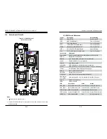
5-7 Connector and Port Definitions
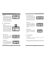
Fan Header
Pin Definitions
Pin# Definition
1
Ground
2
+12V
3
Tachometer
4
PWR Modulation
Fan Headers
The X10DRS has eight fan headers
(Fan1 - Fan8). These 4-pin fans head-
ers are backward compatible with
traditional 3-pin fans (which do not
support fan speed control). Fan speed
is controlled by IPMI. See the table on
the right for pin definitions.
TPM Header/Port 80
A Trusted Platform Module/Port 80
header is located at JTPM1 to provide
TPM support and Port 80 connection.
Use this header to enhance system
performance and data security. See
the table on the right for pin defini
-
tions.
TPM/Port 80 Header
Pin Definitions
Pin # Definition
Pin # Definition
1
LCLK
2
GND
3
LFRAME#
4
<(KEY)>
5
LRESET#
6
+5V (X)
7
LAD 3
8
LAD 2
9
+3.3V
10
LAD1
11
LAD0
12
GND
13
SMB_CLK4
14
SMB_DAT4
15
+3V_DUAL
16
SERIRQ
17
GND
18
CLKRUN# (X)
19
LPCPD#
20
LDRQ# (X)
SATA DOM Power Connectors
Two power connectors for SATA DOM
(Disk On Module) devices are located
at JSD1/JSD2. Connect appropriate
cables here to provide power support
for your DOM devices.
DOM PWR
Pin Definitions
Pin# Definition
1
+5V
2
Ground
3
Ground
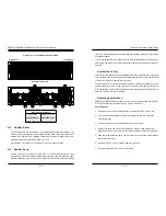
10GbE LAN (TLAN) Ports & IPMI LAN Port
Two 10-Gigabit Ethernet LAN ports (LAN1/2) are located on the I/O back panel.
LAN port 1 can also be used as IPMI LAN for Serial-Over-LAN (SOL) support. All
these ports accept RJ45-type cables. Please refer to the LED Indicator section for
LAN LED information.
VGA/COM1/USB 2.0 Connector (JKVM1)
A VGA/COM1/USB 2.0 connector is located next to LAN2 on the I/O back panel.
JKVM1 provides a video port as well as serial and USB (2.0) connections with
SMCI-proprietary cable (CBL-0218L) connected to JKVM1.
External SAS Port
Two external SAS 3.0 ports are supported by the AOM-S3008-L8-SB add-on
module, which is located next to the JKVM1 connector on the I/O back panel.
Universal Serial Bus (USB)
In addition to the two USB 2.0 ports (USB 1/2) on the I/O back panel, a Type A
connector is also located on the motherboard to provide USB 3.0 support (USB 3,
cables not included). See note below.)
Back Panel USB0/1 (USB2.0)
Pin Definitions
Pin# Definition Pin# Definition
1
+5V
5
+5V
2
USB_PN1
6
USB_PN0
3
USB_PP1
7
USB_PP0
4
Ground
8
Ground
USB3 (USB3.0)
Pin Definitions
Pin#
Description
1
VBUS
2
SSRX-
3
SSRX+
4
Ground
5
SSTX-
6
SSTX+
7
GND_DRAIN
8
D-
9
D+
IPMB
A System Management Bus header
for IPMI 2.0 is located at JIPMB1.
Connect an appropriate cable here to
use the IPMB I
2
C connection on your
system.
IPMB Header
Pin Definitions
Pin# Definition
1
Data
2
Ground
3
Clock
4
No Connection
Summary of Contents for 6038R-DE2CR16L
Page 1: ...USER S MANUAL 1 0a SUPER STORAGE SYSTEM 6038R DE2CR16L ...
Page 6: ...SUPERSTORAGESYSTEM 6038R DE2CR16L User s Manual x Notes ...
Page 17: ...3 4 SUPERSTORAGESYSTEM 6038R DE2CR16L User s Manual Notes ...
Page 45: ...6 10 SUPERSTORAGESYSTEM 6038R DE2CR16L User s Manual Notes ...
Page 69: ...A 2 SUPERSTORAGESYSTEM 6038R DE2CR16L User s Manual Notes ...


