Chapter 5: Advanced Serverboard Setup
5-13
5-12
S
UPER
S
TORAGE
S
YSTEM 2028R-E1CR24L User's Manual
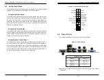
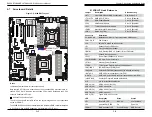
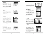
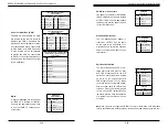
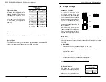
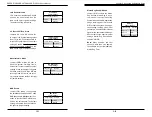
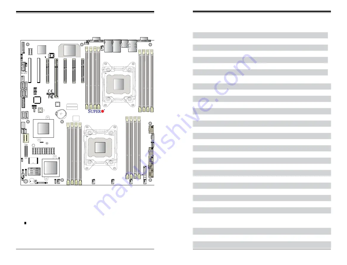
Figure 5-5. X10DRH-iT Layout
5-7 Serverboard Details
Notes
Jumpers not indicated are for test purposes only.
Note that the PCI slots are enabled when their corresponding processors are in-
stalled. "CPU2 Slot 4" indicates that a second CPU must be installed in the CPU2
socket to enable this PCI slot.
" " indicates the position of pin 1.
The LSI 3108 onboard controller chip in the layout image above is not populated
on the X10DRH-iT.
The 2028R-E1CR24L comes pre-installed with a Hardware RAID controller installed
in PCI-E slot 2 and a JBOD expansion port installed in PCI-E slot 1.
X10DRH-iT Quick Reference
Jumper
Description
Default Setting
JBT1
Clear CMOS/Reset BIOS Configuration
See Section 5-9
JI
2
C1/JI
2
C2 SMB to PCI-E Slots
Pins 2-3 (Disabled)
JPB1
BMC Enable/Disable
Pins 1-2 (Enabled)
JPG1
VGA Enable/Disable
Pins 1-2 (Enabled)
JPL1
TLAN1/TLAN2 Enable/Disable
Pins 1-2 (Enabled)
JPME2
Manufacture (ME) Mode Select
Pins 1-2 (Normal)
JWD1
Watch Dog Timer
Pins 1-2 (Reset)
Connector
Description
COM1/COM2
Backplane COM Port1/Front accessible COM2 header
FAN1-6,A, B
Fan Headers
J24
24-pin ATX Main Power Connector
JD1
Speaker/Power LED Header
JF1
Front Control Panel Header
JIPMB1
4-pin External BMC I
2
C Header (for an IPMI card)
JL1
Chassis Intrusion Header
JPI
2
C1
Power Supply SMBbus I
2
C Header
JPWR1/JPWR2 12V 8-pin Power Connectors
JSTBY1
Standby Power Connector
JTPM1
TPM (Trusted Platform Module)/Port 80 Header
LAN1/LAN2
10G-bit Ethernet (TLAN) Ports
IPMI_LAN
Dedicated IPMI LAN (supported by the ASpeed controller)
I-SATA 0-5
SATA 3.0 Ports (supported by Intel PCH)
S-SATA
SATA 3.0 4-port Vertical Connector (supported by Intel SCU)
(I-)SGPIO1/2
Serial Link General Purpose I/O Headers
UID
UID (Unit Identification) Button
USB 0/1 (2.0)
USB 2.0 Ports (rear I/O)
USB 2/3 (2.0)
USB 2.0 Headers
USB 4/5 (3.0)
USB 3.0 Ports (rear I/O)
USB 7/8 (3.0)
USB 3.0 Header
USB 6 (3.0)
Type A USB 3.0 Connector
LED
Description
State
Status
LE1
Rear UID LED
Blue: On
Unit Identified
LE2
Onboard PWR LED
On
Power On
LEDM1
BMC Heartbeat LED
Green: Blinking
BMC Normal
I-S
AT
A5
I-S
AT
A4
I-S
AT
A0
I-S
AT
A1
I-S
AT
A2
I-S
AT
A3
I-SGPIO1 I-SGPIO2
S-SA
TA
JS39
USB0/1
FAN6
FAN5
FA
NB
FANA
FA
N3
FA
N2
FA
N1
JBT1
LEDM
1
LE
1
LEDS5
LEDS6
DS13
JIPMB1
SP1
J2
3
JPS7
JPG1
JBR1
JI2C
2
JI2C
1
JPME
2
JPS1
JWD1
JTPM
1
USB2/3
BIOS
BT
1
JSTBY1
JL
1
JOH1
JD1
JS
1
JF1
JPWR
2
JPWR
1
JPI2C
1
USB4/5
USB6
USB7/8
BIOS
LICENSE
MAC CODE
BAR CODE
(3.0)
(3.0
)
(2.0
)
TPM/PO
RT
80
CPU1 SLOT1 PCI-E 3.0 X8
SAS4-7
COM2
CPU1 SLOT2 PCI-E 3.0 X8
CPU1 SLOT3 PCI-E 3.0 X8
CPU2 SLOT4 PCI-E 3.0 X1
6
CPU2 SLOT5 PCI-E 3.0 X8
CPU2 SLOT6 PCI-E 3.0 X8
UID
P1 DIMMC
1
P1 DIMMC
2
P2 DIMME
1
P1 DIMMD
1
P2 DIMME
2
P1 DIMMD
2
P2 DIMMF
2
P2 DIMMF
1
CPU1
P1 DIMMB
2
P2 DIMMH
2
P1 DIMMA
2
P1 DIMMB
1
P2 DIMMH
1
P1 DIMMA
1
P2 DIMMG
2
VGA
P2 DIMMG
1
LAN2 LAN1
(3.0)
IPMI_LA
N
COM1
PWR I2C
CPU2 SLOT7 PCI-E 3.0 X8
FA
N4
J2
4
X10DRH-C/i(T)
Rev. 1.00
JPB1
JPL1
TFM
LE
2
CPU2
SAS0-3
LSI 3108
SAS CTRL
PCH
BMC
CLOSE 1st
OPEN 1st
CLOSE 1st
OPEN 1st
Battery
LAN CTRL
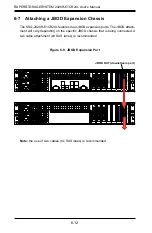
JBOD ExpansionPort
Controller Card
Summary of Contents for 2028R-E1CR24L
Page 1: ...SUPER STORAGE SYSTEM 2028R E1CR24L USER S MANUAL 1 0a ...
Page 6: ...SUPERSTORAGESYSTEM 2028R E1CR24L User s Manual Notes x ...
Page 10: ...1 6 SUPERSTORAGESYSTEM 2028R E1CR24L User s Manual Notes ...
Page 16: ...2 10 SUPERSTORAGESYSTEM 2028R E1CR24L User s Manual Notes ...
Page 19: ...3 4 SUPERSTORAGESYSTEM 2028R E1CR24L User s Manual Notes ...
Page 77: ...7 48 SUPERSTORAGESYSTEM 2028R E1CR24L User s Manual Notes ...
Page 79: ...A 2 SUPERSTORAGESYSTEM 2028R E1CR24L User s Manual Notes ...
Page 82: ...B 4 SUPERSTORAGESYSTEM 2028R E1CR24L User s Manual Notes ...

