background image

7-4

S

UPER

S

TORAGE

S

YSTEM 2028R-E1CR24H User's Manual

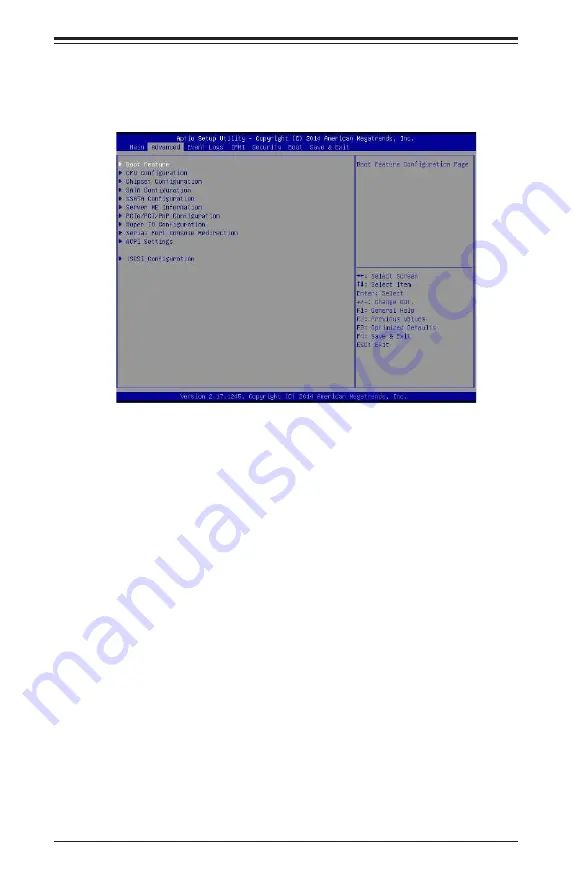
7-3   Advanced Setup Configurations

Use the arrow keys to select Advanced setup and press <Enter> to access the 

submenu items:

Warning: Use caution when changing the Advanced settings. An incorrect value, a 

very high DRAM frequency or an incorrect BIOS timing setting may cause the system 

to malfunction. If this occurs, restore the setting to the manufacture default setting.

Boot Feature

Quiet Boot

Use this feature to select the screen display between POST messages or the OEM 

logo at bootup. Select Disabled to display the POST messages. Select Enabled 

to display the OEM logo instead of the normal POST messages. The options are 

Enabled and Disabled. 

AddOn ROM Display Mode

Use this item to set the display mode for the Option ROM. Select Keep Current to 

use the current AddOn ROM display setting. Select Force BIOS to use the Option 

ROM display mode set by the system BIOS. The options are Force BIOS and 

Keep Current. 

Bootup Num-Lock State

Use this item to set the Power-on state for the Numlock key. The options are Off 

and On.

Summary of Contents for 2028R-E1CR24H

Page 1: ...SUPER STORAGE SYSTEM 2028R E1CR24H USER S MANUAL 1 0 ...

Page 2: ...of any such disputes Super Micro s total liability for all claims will not exceed the price paid for the hardware product FCC Statement This equipment has been tested and found to comply with the limits for a Class A digital device pursuant to Part 15 of the FCC Rules These limits are designed to provide reasonable protection against harmful interference when the equipment is operated in a commerc...

Page 3: ...and the SC216BE1C R920LPB chassis Chapter 2 Server Installation This chapter describes the steps necessary to install the 2028R E1CR24H into a rack and check out the server configuration prior to powering up the system If your server was ordered without processor and memory components this chapter will refer you to the appropriate sections of the manual for their installation Chapter 3 System Inte...

Page 4: ...reconfig uring the serverboard Chapter 6 Advanced Chassis Setup Refer to Chapter 6 for detailed information on the SC216BE1C R920LPB chassis You should follow the procedures given in this chapter when installing removing or reconfiguring hard drives and when replacing system power supply units and cooling fans Chapter 7 BIOS The BIOS chapter includes an introduction to BIOS and provides detailed i...

Page 5: ...Notes Preface v ...

Page 6: ... Unpacking the System 2 1 2 3 Preparing for Setup 2 1 Choosing a Setup Location 2 1 2 4 Warnings and Precautions 2 2 Rack Precautions 2 2 Server Precautions 2 2 Rack Mounting Considerations 2 3 Ambient Operating Temperature 2 3 Reduced Airflow 2 3 Mechanical Loading 2 3 Circuit Overloading 2 3 Reliable Ground 2 3 2 5 Rack Mounting Instructions 2 4 Identifying the Sections of the Rack Rails 2 4 Loc...

Page 7: ...it Breaker 4 5 Power Disconnection Warning 4 6 Equipment Installation 4 8 Restricted Area 4 9 Battery Handling 4 10 Redundant Power Supplies 4 12 Backplane Voltage 4 13 Comply with Local and National Electrical Codes 4 14 Product Disposal 4 15 Hot Swap Fan Warning 4 16 Power Cable and AC Adapter 4 18 Chapter 5 Advanced Serverboard Setup 5 1 Handling the Serverboard 5 1 Precautions 5 1 5 2 Connecti...

Page 8: ...e Devices 6 1 Precautions 6 1 6 2 Control Panel 6 2 6 3 Removing the Chassis Cover 6 3 6 4 System Cooling 6 4 System Fans 6 4 System Fan Failure 6 4 Replacing System Fans 6 4 Air Shrouds 6 5 Installing the Air Shrouds in the Chassis 6 5 6 5 Drive Bay Installation Removal 6 7 Accessing the Drive Bays 6 7 Hard Drive Installation 6 7 6 6 Power Supply 6 10 6 7 Attaching a JBOD Expansion Chassis 6 12 C...

Page 9: ...ix Table of Contents 7 5 IPMI 7 42 7 6 Security Settings 7 44 7 7 Boot Settings 7 45 7 8 Save Exit 7 46 Appendix A BIOS POST Error Codes Appendix B System Specifications ...

Page 10: ...SUPERSTORAGESYSTEM 2028R E1CR24H User s Manual Notes x ...

Page 11: ... One air shroud MCP 310 29001 0N SATA Accessories One SATA backplane BPN SAS3 216EL1 Twenty four 2 5 hard drive carriers MCP 220 00047 0B 12 Gb s Hardware RAID controller AOC S3108L H8IR JBOD expansion port AOM SAS3 8I8E LP One rackmount kit MCP 290 00053 0N Note For your system to work properly please follow the links below to download all necessary drivers utilities and the user s manual for you...

Page 12: ...rage Controller An LSI 3108 controller card is included in the system to support up to 240 SATA 3 0 SAS 3 0 hard drives RAID 0 1 5 6 10 50 and 60 supported The SATA SAS drives are hot swappable units Serial ATA A SATA controller is integrated into the chipset to provide 10 SATA 3 0 6 Gbps ports I SATA0 5 supported by the Intel PCH and a vertical 4 port S SATA con nection supported by the Intel SCU...

Page 13: ... allows you to replace a failed power supply without shutting down the system Hard Drives The SC216BE1C R920LPB chassis was designed to support 24 hot swappable SAS or SATA hard drives Front Control Panel The control panel on the SuperServer 2028R E1CR24N provides you with system monitoring and control LEDs indicate system power HDD activity network activity and power supply failure A Universal In...

Page 14: ...A CONN BMC Boot Flash DDR3 5 PHASE 145W P1 P1 P0 VR12 5 P0 QPI 9 6G 2 x PCI E X8 G3 LAN REVERSE 2 I M D 2 I M D CPU1 CPU2 QPI 9 6G 5 PHASE 145W VR12 5 X540 I350 LAN1 2 PCI E X8 G2 SLOT 4 SLOT 5 PCI E X16 PCI E X8 SLOT 6 PCI E X8 PCI E X8 G3 2 x PCI E X8 G3 PCI E X16 G3 1 2 3 1 3 1 8 2 8 6 7 8 9 VCCP1 12v PVCCIO 1 05 0 95 from 3 3v PCI E X8 SLOT 7 LSI 3108 PCI E X8 G3 PCI E X8 2 SLOT 1 PCI E X8 SLO...

Page 15: ...pe Address Super Micro Computer B V Het Sterrenbeeld 28 5215 ML s Hertogenbosch The Netherlands Tel 31 0 73 6400390 Fax 31 0 73 6416525 Email sales supermicro nl General Information support supermicro nl Technical Support rma supermicro nl Customer Support Website www supermicro nl Asia Pacific Address Super Micro Computer Inc 3F No 150 Jian 1st Rd Zhonghe Dist New Taipei City 235 Taiwan R O C Tel...

Page 16: ...1 6 SUPERSTORAGESYSTEM 2028R E1CR24H User s Manual Notes ...

Page 17: ...n a suitable location for the rack unit that will hold the SuperServer 2028R E1CR24H It should be situated in a clean dust free area that is well ventilated Avoid areas where heat electrical noise and electromagnetic fields are generated You will also need it placed near a grounded power outlet Read the Rack and Server Precautions in the next section 2 3 Preparing for Setup The box the SuperServer...

Page 18: ... together Always make sure the rack is stable before extending a component from the rack You should extend only one component at a time extending two or more si multaneously may cause the rack to become unstable Server Precautions Review the electrical and general safety precautions in Chapter 4 Determine the placement of each component in the rack before you install the rails Install the heaviest...

Page 19: ...ssible overloading of circuits might have on overcurrent protection and power supply wiring Appropriate consideration of equipment nameplate ratings should be used when addressing this concern Reliable Ground A reliable ground must be maintained at all times To ensure this the rack itself should be grounded Particular attention should be given to power supply connec tions other than the direct con...

Page 20: ...the Sections of the Rack Rails The chassis package includes two rail assemblies in the rack mounting kit Each assembly consists of three sections An inner chassis rail which secures directly to the chassis an outer rail that secures to the rack and a middle rail which extends from the outer rail These assemblies are specifically designed for the left and right side of the chassis Figure 2 1 Identi...

Page 21: ...g Releasing the Inner Rail Releasing Inner Rail from the Outer Rails 1 Identify the left and right outer rail assemblies as described on page 6 4 2 Pull the inner rail out of the outer rail until it is fully extended as illustrated below 3 Press the locking tab down to release the inner rail 4 Repeat steps 1 3 for the second outer rail Slide rail mounted equipment is not to be used as a shelf or a...

Page 22: ...eft and right inner rails have been correctly identified 2 Place the inner rail firmly against the side of the chassis aligning the hooks on the side of the chassis with the holes in the inner rail 3 Slide the inner rail forward toward the front of the chassis until the rail clicks into the locked position which secures the inner rail to the chassis 4 Secure the inner rail to the chassis with the ...

Page 23: ...t of the rack If necessary use screws to secure the outer rails to the rack as illustrated above 4 Pull out the rear of the outer rail adjusting the length until it fits within the posts of the rack 5 Hang the hooks of the rear portion of the outer rail onto the slots on the rear of the rack If necessary use screws to secure the rear of the outer rail to the rear of the rack 6 Repeat steps 1 5 for...

Page 24: ...s at the front locking position of the middle rail 4 Align the chassis inner rails with the front of the middle rails 5 Slide the inner rails on the chassis into the middle rails keeping the pressure even on both sides until the locking tab of the inner rail clicks into the front of the middle rail locking the chassis into the fully extended position 6 Depress the locking tabs of both sides at the...

Page 25: ...stall the whole rail assembly onto the rack as described on page 2 7 2 Release the inner rail without retracting the middle rail 3 Install the inner rails on the chassis as previously described on page 2 6 4 Install the chassis onto the middle rail as described in the previous section Note The figure above is for illustration purposes only Always install servers to the bottom of the rack first ...

Page 26: ...2 10 SUPERSTORAGESYSTEM 2028R E1CR24H User s Manual Notes ...

Page 27: ... a reset button and a power on off button Reset Use the reset button to reboot the system Power This is the main power button which is used to apply or turn off the main system power Turning off system power with this button removes the main power but keeps standby power supplied to the system Therefore the system power cord should be unplugged before performing service 3 3 Control Panel LEDs The ...

Page 28: ... an overheat condition which may be caused by cables obstructing the airflow in the system or the ambient room temperature being too warm Check the routing of the cables and make sure all fans are present and operating normally You should also check to make sure that the chassis covers are installed Finally verify that the heatsinks are installed properly see Chapter 5 This LED will remain flashin...

Page 29: ...The chassis includes externally accessible SAS SATA drives Each drive carrier displays two status LEDs on the front of the carrier LED LED Color State Status Activity LED Blue Solid On SAS drive installed Blue Blinking I O activity Blue Dark off Sata drive installed or empty run I O to verify Status LED Red Solid On Failed drive for SAS SATA Red Blinking at 1 Hz Rebuild drive for SAS SATA Red Blin...

Page 30: ...3 4 SUPERSTORAGESYSTEM 2028R E1CR24H User s Manual Notes ...

Page 31: ...r configuring components in the Supermicro chassis These warnings may also be found on our website at http www supermicro com about policies safety_information cfm Warning Definition Warning This warning symbol means danger You are in a situation that could cause bodily injury Before you work on any equipment be aware of the hazards involved with electrical circuitry and be familiar with standard ...

Page 32: ...rará el número que le ayudará a encontrar el texto traducido en el apartado de traducciones que acompaña a este dispositivo GUARDE ESTAS INSTRUCCIONES IMPORTANTES INFORMATIONS DE SÉCURITÉ Ce symbole d avertissement indique un danger Vous vous trouvez dans une situation pouvant entraîner des blessures ou des dommages corporels Avant de travailler sur un équipement soyez conscient des dangers liés a...

Page 33: ... aan enige apparatuur gaat werken dient u zich bewust te zijn van de bij een elektrische installatie betrokken risico s en dient u op de hoogte te zijn van de standaard procedures om ongelukken te voorkomen Gebruik de nummers aan het eind van elke waarschuwing om deze te herleiden naar de desbetreffende locatie BEWAAR DEZE INSTRUCTIES ً ف اًك أى ٌوكي حالة ً ف تتسبب اصابة جسذٌة الزهز هذا ًٌ ٌع خطز ...

Page 34: ...Stromquelle die Installationsanweisungen lesen Advertencia Lea las instrucciones de instalación antes de conectar el sistema a la red de alimentación Attention Avant de brancher le système sur la source d alimentation consulter les directives d installation ال إرشادات اقر تركيب توصيل قبل إلى النظام للطاقة مصدر לקרוא יש למקור המערכת חיבור לפני התקנה הוראות את מתח 시스템을 전원에 연결하기 전에 설치 안내를 읽어주십시오 Waar...

Page 35: ...äude ein Kurzschluss bzw Überstromschutz installiert ist Stellen Sie sicher dass der Nennwert der Schutzvorrichtung nicht mehr als 250 V 20 A beträgt Advertencia Este equipo utiliza el sistema de protección contra cortocircuitos o sobrecorrientes del edificio Asegúrese de que el dispositivo de protección no sea superior a 250 V 20 A Attention Pour ce qui est de la protection contre les courts circ...

Page 36: ...源はすべてのソースから切断され 電源コードは電源モジュールから取り 外す必要があります 警告 在你打开机箱并安装或移除内部器件前 必须将系统完全断电 并移除电源线 警告 在您打開機殼安裝或移除內部元件前 必須將系統完全斷電 並移除電源線 경고 이 제품은 전원의 단락 과전류 방지에 대해서 전적으로 건물의 관련 설비에 의존합니다 보호장치의 정격이 반드시 250V 볼트 20A 암페어 를 초과하지 않도록 해야 합니다 Waarschuwing Dit product is afhankelijk van de kortsluitbeveiliging overspanning van uw electrische installatie Controleer of het beveiligde aparaat niet groter gedimensioneerd is dan...

Page 37: ... sources de puissance ainsi que de son cordon d alimentation secteur avant d accéder à l intérieur du chassis pour installer ou enlever des composants de systéme חשמלי ניתוק מפני אזהרה אזהרה החשמל מקורות מכל המערכת את לנתק יש להסיר ויש מהספק החשמלי כבל את התקנ לצורך המארז של הפנימי לחלק גישה לפני ת הסר או ת רכיבים فصم يجب اننظاو جميع من مصادر انطاقت وإزانت انكهرباء سهك من وحدة امداد انطاقت قبم إنى...

Page 38: ...enen dieser Ausrüstung sollte nur geschultem qualifiziertem Personal gestattet werden Advertencia Solamente el personal calificado debe instalar reemplazar o utilizar este equipo Attention Il est vivement recommandé de confier l installation le remplacement et la maintenance de ces équipements à des personnels qualifiés et expérimentés אזהרה רש בלבד מוסמך צוות את להחליף להתקין אי הציוד עבור שירות ...

Page 39: ...t beschränktem Zutritt vorgesehen Der Zutritt zu derartigen Bereichen ist nur mit einem Spezialwerkzeug Schloss und Schlüssel oder einer sonstigen Sicherheitsvorkehrung möglich Advertencia Esta unidad ha sido diseñada para instalación en áreas de acceso restringido Sólo puede obtenerse acceso a una de estas áreas mediante la utilización de una herramienta especial cerradura con llave u otro medio ...

Page 40: ...池 警告 電池更換不當會有爆炸危險 請使用製造商建議之相同或功能相當的電池更換原有 電池 請按照製造商的說明指示處理廢棄舊電池 מוגבלת גישה עם אזור אזהרה בעזרת ניתנת הגישה גישה הגבלת בהם שיש באזורים היחידה את להתקין יש וכד מנעול מפתח בלבד אבטחה כלי تخصيص انىحذة هذه ٍ ف نتركُبها مناطق محظورة تم انىص َمكن ً إن ىل منطقت محظورة فقط استخذاو خالل من خاصت أداة أو ٌ أ نال أخري وسُهت مألما ومفتاح قفم 경고 이 장치는 접근이 제한된 구역에 설치하도록 되어있습니다 특수도구 잠금 장치 및 키 또는 기타 보안 수단을 통해서만 접근...

Page 41: ...ipo o el equivalente recomendado por el fabricante Desechar las baterías gastadas según las instrucciones del fabricante אזהרה סכנת קיימת פיצוץ תקינה לא בדרך והוחלפה במידה הסוללה של להחליף יש בסוג הסוללה את מ התואם חברת מומל יצרן צת הסוללות סילוק המשומשות לבצע יש היצרן הוראות לפי خطر هناك من اسحبذال حالة في انفجار البطارية صحيحة غير بطريقة فعليل البطارية اسحبذال فقط النىع بنفس يعادلها ما أو مما أو...

Page 42: ...fuhr haben Um sicherzustellen dass der Einheit kein trom zugeführt wird müssen alle Verbindungen entfernt werden Advertencia Puede que esta unidad tenga más de una conexión para fuentes de alimentación Para cortar por completo el suministro de energía deben desconectarse todas las conexiones Attention Cette unité peut avoir plus d une connexion d alimentation Pour supprimer toute tension et tout c...

Page 43: ...ten auf der Rückwandplatine gefährliche Spannungen oder Energien auf Vorsicht bei der Wartung Advertencia Cuando el sistema está en funcionamiento el voltaje del plano trasero es peligroso Tenga cuidado cuando lo revise قد لهذا يكون ال جهاز اتصاالت عدة بوحدات الطاقة امداد إزالة يجب االتصاالت كافة لعسل ال وحدة عن الكهرباء 경고 이 장치에는 한 개 이상의 전원 공급 단자가 연결되어 있을 수 있습니다 이 장치에 전원을 차단하기 위해서는 모든 연결 단자를 제거해야...

Page 44: ... الكهزبائي التيار على المىجىدة أوالطاقة اللىحة يكىن عندما النظام يعمل عند حذرا كه خدمة الجهاس هذا 경고 시스템이 동작 중일 때 후면판 Backplane 에는 위험한 전압이나 에너지가 발생 합니다 서비스 작업 시 주의하십시오 Waarschuwing Een gevaarlijke spanning of energie is aanwezig op de backplane wanneer het systeem in gebruik is Voorzichtigheid is geboden tijdens het onderhoud האחורי בפנל מתח אז הרה במהלך להיזהר יש המערכת תפעול בזמן האחורי בפנל מתח...

Page 45: ... התקנת והארציים המקומיים החשמל לחוקי תואמת להיות חייבת הציוד المعدات تركيب الكهربائية لل يمتثل أن يجب قىاويه والىطىية المحلية المتعلقة بالكهرباء Advertencia La instalacion del equipo debe cumplir con las normas de electricidad locales y nacionales Attention L équipement doit être installé conformément aux normes électriques nationales et locales 경고 현 지역 및 국가의 전기 규정에 따라 장비를 설치해야 합니다 Waarschuwing Bi...

Page 46: ...Hot Swap Fan Warning Warning The fans might still be turning when you remove the fan assembly from the chassis Keep fingers screwdrivers and other objects away from the openings in the fan assembly s housing ファン ホッ トスワップの警告 シャーシから冷却ファン装置を取り外した際 ファンがまだ回転している可能性があり ます ファンの開口部に 指 ドライバー およびその他のものを近づけないで下さい 警告 המוצר סילוק אזהרה ו להנחיות בהתאם להיות חייב זה מוצר של סופי סילוק המדינה חוקי النهائي التخلص...

Page 47: ...品太靠近风扇 警告 當您從機架移除風扇裝置 風扇可能仍在轉動 小心不要將手指 螺絲起子和其他 物品太靠近風扇 Warnung Die Lüfter drehen sich u U noch wenn die Lüfterbaugruppe aus dem Chassis genommen wird Halten Sie Finger Schraubendreher und andere Gegenstände von den Öffnungen des Lüftergehäuses entfernt Advertencia Los ventiladores podran dar vuelta cuando usted quite ell montaje del ventilador del chasis Mandtenga los dedos los destornilladores y ...

Page 48: ...它线 材或适配器可能会引起故障或火灾 除了Supermicro所指定的产品 电气用品和材 料安全法律规定禁止使用未经UL或CSA认证的线材 线材上会显示UL CSA符号 警告 安裝此產品時 請使用本身提供的或指定的連接線 電源線和電源適配器 使用其它線 材或適配器可能會引起故障或火災 除了Supermicro所指定的產品 電氣用品和材 料安全法律規定禁止使用未經UL或CSA認證的線材 線材上會顯示UL CSA符號 Warnung Bei der Installation des Produkts die zur Verfügung gestellten oder benannt Anschlusskabel Stromkabel und Netzteile Verwendung anderer Kabel und Adapter kann zu einer Fehlfunktion ode...

Page 49: ...sur le code pour tous les autres appareils électriques que les produits désignés par Supermicro seulement ומתא חשמליים מ י AC אזהרה ומתאמים ספקים בכבלים להשתמש יש המוצר את מתקינים כאשר AC אשר או לתקלה לגרום יכול אחר מתאם או כבל בכל שימוש כך לשם וסופקו נועדו בט וחוקי חשמל במכשירי שימוש חוקי פי על חשמלי קצר איסור קיים יחות ב המוסמכים בכבלים להשתמש UL ב או CSA של קוד עליהם מופיע כשאר UL CSA אחר חשמלי...

Page 50: ...zen kabels stroomkabels en adapters Het gebruik van andere kabels en adapters kan leiden tot een storing of een brand Elektrisch apparaat en veiligheidsinformatiebladen wet verbiedt het gebruik van UL of CSA gecertificeerde kabels die UL of CSA die op de code voor andere elektrische apparaten dan de producten die door Supermicro alleen ...

Page 51: ...carefully see previous chapter To prevent the serverboard from bending keep one hand under the center of the board to support it when handling The following measures are generally sufficient to protect your equipment from electric static discharge Precautions Use a grounded wrist strap designed to prevent Electrostatic Discharge ESD Touch a grounded metal object before removing any board from its ...

Page 52: ... on page 5 10 for connector locations Connecting Power Cables The X10DRH iT has a 24 pin primary power supply connector J24 for connection to the ATX power supply In addition there are two 8 pin 12V processor power con nectors JPWR1 and JPWR2 that must be connected to your power supply See Section 5 9 for power connector pin definitions Connecting the Control Panel JF1 contains header pins for var...

Page 53: ...2 Dedicated IPMI LAN 7 TLAN Port 1 3 USB Port 1 8 TLAN Port 2 4 USB Port 0 9 VGA Port 5 USB Port 5 1 9 1 8 7 5 6 3 4 2 1 2 Ground 19 20 NMI X X FP PWRLED 3 3 V HDD LED UID Switch NIC1 Link LED NIC1 Activity LED NIC2 Link LED NIC2 Activity LED UID LED OH Fan Fail PWR Fail LED Power Fail LED 3 3V Reset Button Power Button Ground Ground Note a UID Unit Identifier button and LED is located to the righ...

Page 54: ...ng re moving or changing any hardware components Make sure that you install the processor into the CPU socket before you install the CPU heatsink If you buy a CPU separately make sure that you use an Intel certified multi directional heatsink only Make sure to install the serverboard into the chassis before you install the CPU heatsinks When receiving a serverboard without a processor pre installe...

Page 55: ... remove the WARNING plastic cap from the socket 5 Use your thumb and index finger to hold the CPU by its edges Align the CPU keys which are semi circle cutouts against the socket keys 6 Once they are aligned carefully lower the CPU straight down into the socket Do not drop the CPU on the socket Do not move the CPU horizontally or vertically and do not rub the CPU against any pins of the socket whi...

Page 56: ...e load plate again and double check that the CPU is aligned properly 7 With the CPU in the socket in spect the four corners of the CPU to make sure that they are flush with the socket 8 Close the load plate Lock the lever labeled Close 1st then lock the lever labeled Open 1st Use your thumb to gently push the load levers down until the lever locks OPEN1st OPEN1st Lever Lock Push down and lock the ...

Page 57: ...4 Figure 5 3 Installing a Heatsink Removing the Heatsink Warning We do not recommend that the CPU or the heatsink be removed However if you do need to uninstall the heatsink please follow the instructions below to uninstall the heatsink to prevent damage done to the CPU or the CPU socket 1 Unscrew the heatsink screws from the serverboard in the sequence as shown in the illustration above 2 Gently ...

Page 58: ...ber of DIMMs into the memory slots starting with P1 DIMMA1 See the Memory Installation Tables on the following pages 2 Insert each DIMM module vertically into its slot Pay attention to the notch along the bottom of the module to avoid installing incorrectly see Figure 5 3 3 Use your thumbs to gently press down on both ends of the DIMM module until it snaps into place in the slot Repeat for all mod...

Page 59: ...1 CPU 4 DIMMs CPU1 P1 DIMMA1 P1 DIMMB1 P1 DIMMC1 P1 DIMMD1 1 CPU 6 or 8 DIMMs CPU1 P1 DIMMA1 P1 DIMMB1 P1 DIMMC1 P1 DIMMD1 any pair of P1 DIMMA2 P1 DIMMB2 P1 DIMMC2 P1 DIMMD2 slots 2 CPUs 4 DIMMs CPU1 CPU2 P1 DIMMA1 P1 DIMMB1 P2 DIMME1 P2 DIMMF1 2 CPUs 6 DIMMs CPU1 CPU2 P1 DIMMA1 P1 DIMMB1 P1 DIMMC1 P1 DIMMD1 P2 DIMME1 P2 DIMMF1 2 CPUs 8 DIMMs CPU1 CPU2 P1 DIMMA1 P1 DIMMB1 P1 DIMMC1 P1 DIMMD1 P2 D...

Page 60: ...ODE BAR CODE X10DRH C i T Rev 1 00 BIOS LICENSE MAC CODE BAR CODE X10DRH C i T Rev 1 00 6 5 BIOS LICENSE MAC CODE BAR CODE X10DRH C i T Rev 1 00 7 8 BIOS LICENSE MAC CODE BAR CODE X10DRH C i T Rev 1 00 BIOS LICENSE MAC CODE BAR CODE X10DRH C i T Rev 1 00 BIOS LICENSE MAC CODE BAR CODE X10DRH C i T Rev 1 00 10 9 BIOS LICENSE MAC CODE BAR CODE X10DRH C i T Rev 1 00 11 12 13 14 15 16 ...

Page 61: ...BOD Expansion Slot2 CPU1 HW RAID Controller Slot3 CPU1 PCI Express 3 0 x8 slot from CPU1 Slot4 CPU2 PCI Express 3 0 x16 slot from CPU2 Slot5 CPU2 PCI Express 3 0 x8 slot from CPU2 Slot6 CPU2 PCI Express 3 0 x8 slot from CPU2 Slot7 CPU2 PCI Express 3 0 x8 slot from CPU2 INTEL CONFIDENTIAL Intel and the Intel logo are trademarks or registered trademarks of Intel Corporation or its subsidiaries in th...

Page 62: ...SATA JS39 USB0 1 FAN6 FAN5 FANB FANA FAN3 FAN2 FAN1 JBT1 LEDM1 LE1 LEDS5 LEDS6 DS13 JIPMB1 SP1 J23 JPS7 JPG1 JBR1 JI2C2 JI2C1 JPME2 JPS1 JWD1 JTPM1 USB2 3 BIOS BT1 JSTBY1 JL1 JOH1 JD1 JS1 JF1 JPWR2 JPWR1 JPI2C1 USB4 5 USB6 USB7 8 BIOS LICENSE MAC CODE BAR CODE 3 0 3 0 2 0 TPM PORT80 CPU1 SLOT1 PCI E 3 0 X8 SAS4 7 COM2 CPU1 SLOT2 PCI E 3 0 X8 CPU1 SLOT3 PCI E 3 0 X8 CPU2 SLOT4 PCI E 3 0 X16 CPU2 SL...

Page 63: ...External BMC I2 C Header for an IPMI card JL1 Chassis Intrusion Header JPI2 C1 Power Supply SMBbus I2 C Header JPWR1 JPWR2 12V 8 pin Power Connectors JSTBY1 Standby Power Connector JTPM1 TPM Trusted Platform Module Port 80 Header LAN1 LAN2 10G bit Ethernet TLAN Ports IPMI_LAN Dedicated IPMI LAN supported by the ASpeed controller I SATA 0 5 SATA 3 0 Ports supported by Intel PCH S SATA SATA 3 0 4 po...

Page 64: ... 20 Res NC 8 PWR_OK 21 5V 9 5VSB 22 5V 10 12V 23 5V 11 12V 24 COM 12 3 3V Reset Button Pin Definitions JF1 Pin Definition 3 Reset 4 Ground Power Button Pin Definitions JF1 Pin Definition 1 Power Signal 2 Ground Secondary Power Connector JPWR1 and JPWR2 must also be connected to the power supply See the table on the right for pin defini tions Required Connection 12V 8 pin Power Pin Definitions Pins...

Page 65: ...nk HDD LED Pin Definitions JF1 Pin Definition 13 UID Switch 14 HD Active NIC2 LAN2 LED The LED connections for LAN2 are on pins 9 and 10 of JF1 Attach an LED cable to display network activ ity See the table on the right for pin definitions NIC1 LED Pin Definitions JF1 Pin Definition 11 Activity 12 Link NIC1 LAN1 LED The LED connections for LAN1 are on pins 11 and 12 of JF1 Attach an LED cable to d...

Page 66: ...in Definitions JF1 Pin Definition 19 Control 20 Ground Fan Header Pin Definitions FAN1 6 FAN A FAN B Pin Definition 1 Ground Black 2 12V Red 3 Tachometer 4 PWR Modulation Power On LED The Power On LED connector is lo cated on pins 15 and 16 of JF1 use JLED for a 3 pin connector This connection is used to provide LED indication of power being supplied to the system See the table on the right for pi...

Page 67: ... are used to communicate with the enclosure management chip on the backplane T SGPIO1 2 support the I SATA ports and S SGPIO1 supports the S SATA ports See the table on the right for pin definitions SGPIO Header Pin Definitions Pin Definition Pin Definition 1 NC 2 NC 3 Ground 4 DATA Out 5 Load 6 Ground 7 Clock 8 NC NC No Connection Speaker Connector Pin Settings Pin Setting Definition Pin 4 P5V Pi...

Page 68: ...agement Bus header for IPMI 2 0 is located at JIPMB1 Connect the appropriate cable here to use the IPMB I2 C connection on your system IPMB Header Pin Definitions Pin Definition 1 Data 2 Ground 3 Clock 4 No Connection Back Panel USB 0 1 2 0 Pin Definitions Pin Definition Pin Definition 1 5V 5 5V 2 USB_PN1 6 USB_PN0 3 USB_PP1 7 USB_PP0 4 Ground 8 Ground Front Panel USB 2 3 2 0 Pin Definitions Pin D...

Page 69: ... need of service Note UID can also be triggered via IPMI For more information on IPMI please refer to the IPMI User s Guide posted on our website at http www supermicro com UID Switch Pin Definition 1 Ground 2 Ground 3 Button In 4 Button In UID LED Status Color State Status Blue On Unit Identified DOM Power Connectors Two power connectors for SATA DOM Disk On Module devices are located at JSD1 JSD...

Page 70: ... Pin Definition Pin Definition 1 LCLK 2 GND 3 LFRAME 4 KEY 5 LRESET 6 5V X 7 LAD 3 8 LAD 2 9 3 3V 10 LAD1 11 LAD0 12 GND 13 SMB_CLK4 14 SMB_DAT4 15 3V_DUAL 16 SERIRQ 17 GND 18 CLKRUN X 19 LPCPD 20 LDRQ X Serial Ports Two serial ports are included on the serverboard COM1 is a rear I O port and COM2 is a header located near PCI E slot 1 which may be used front front access Ethernet Ports Two 10Gb Et...

Page 71: ...3 2 1 CMOS Clear JBT1 is used to clear CMOS which will also clear any passwords Instead of pins this jumper consists of contact pads to prevent accidentally clearing the contents of CMOS To clear CMOS 1 First power down the system and unplug the power cord s 2 With the power disconnected short the CMOS pads with a metal object such as a small screwdriver 3 Remove the screwdriver or shorting device...

Page 72: ...umper Settings Jumper Setting Definition Pins 1 2 Enabled Pins 2 3 Disabled BMC Enable Jumper JPB1 allows you to enable the embedded the ASpeed AST 2400 BMC Baseboard Management Con troller to provide IPMI 2 0 KVM sup port on the serverboard The default setting is Enabled See the table on the right for jumper settings BMC Enable Jumper Settings Jumper Setting Definition Pins 1 2 Enabled Pins 2 3 D...

Page 73: ...D to reset the system if an appli cation hangs Jumping pins 2 3 will generate a non maskable interrupt signal for the application that hangs See the table on the right for jumper settings Watch Dog must also be enabled in BIOS Note When enabled the user needs to write their own applica tion software in order to disable the Watch Dog Timer Watch Dog Jumper Settings Jumper Setting Definition Pins 1 ...

Page 74: ...to unplug the power cable before removing or adding any components See the table on the right for more details Dedicated IPMI LAN LEDs A dedicated IPMI LAN is also located on the I O backplane The amber LED on the right indicates activity while the green LED on the left indicates the speed of the connection See the table at right for more information BMC Heartbeat LED A BMC Heartbeat LED is locate...

Page 75: ...se refer to the Intel SATA HostRAID User s Guide posted on our website at http www supermicro com SATA Ports There are ten SATA 3 0 ports included on the serverboard Six ports I SATA 0 5 are supported by the Intel PCH C612 while the other four are supported by the Intel SCU and are located on a vertical S SATA connector ...

Page 76: ...f preferred Another option is to go to the Supermicro website at http www supermicro com products Find the product page for your serverboard here where you may down load individual drivers and utilities After creating a CD DVD with the ISO files insert the disk into the CD DVD drive on your system and the display shown in Figure 5 6 should appear Note Click the icons showing a hand writing on pape...

Page 77: ...ent versions and can be used with Nagios to maximize your system monitoring needs With SuperDoctor 5 Man agement Server SSM Server you can remotely control power on off and reset chassis intrusion for multiple systems with SuperDoctor 5 or IPMI SD5 Manage ment Server monitors HTTP FTP and SMTP services to optimize the efficiency of your operation Note The default User Name and Password for SuperDo...

Page 78: ...ccur if this practice is not strictly followed Figure 5 8 Installing the Onboard Battery OR Please handle used batteries carefully Do not damage the battery in any way a damaged battery may release hazardous materials into the environment Do not discard a used battery in the garbage or a public landfill Please comply with the regulations set up by your local hazardous waste management agency to di...

Page 79: ... To prevent damage to any printed circuit boards PCBs it is important to handle them very carefully The following measures are generally sufficient to protect your equipment from ESD damage Precautions Use a grounded wrist strap designed to prevent static discharge Touch a grounded metal object before removing any board from its antistatic bag Handle a board by its edges only do not touch its comp...

Page 80: ...le from JF1 on the serverboard to the Control Panel PCB printed circuit board Make sure the red wire plugs into pin 1 on both connectors Pull all excess cabling out of the airflow path The LEDs inform you of system status See Chapter 3 for details on the LEDs and the control panel buttons Details on JF1 can be found in Chapter 5 Hard Drives 24 Control Panel I O Ports see Figure 5 2 Optional 2 5 Ho...

Page 81: ... to remove the cover from the locked position Press both tabs at the same time 2 Once the top cover is released from the locked position slide the cover toward the rear of the chassis 3 Lift the cover off the chassis Warning Except for short periods of time do NOT operate the server without the cover in place The chassis cover must be in place to allow proper airflow and prevent overheating Releas...

Page 82: ...est convenience with the same type and model the system can continue to run with a failed fan Remove the top chassis cover while the system is still running to determine which of the fans has failed Replacing System Fans Replacing a System Fan 1 If necessary open the chassis while the power is running to determine which fan requires changing Never run the server for an extended period of time with...

Page 83: ... heatsink and memory are all properly installed 3 If necessary move any cables that interfere with the air shroud placement 4 Place the air shroud in the chassis The air shroud fits just behind the three fans in the fan rack Slide the air shroud into the grooves just behind the fan rack Note that some serverboards may require the air shroud to be modified to fit over the serverboard The SC216 chas...

Page 84: ... Install the additional air shroud if necessary Installing the Additional Air Shroud 1 Remove the left side break away piece of the main air shroud 2 Slide the additional air shroud into the chassis before installing the main air shroud 3 Install the main air shroud as directed on the previous page Figure 6 4 Installing the Air Shroud ...

Page 85: ...o help promote proper airflow for the drive bays For this reason even empty carriers without drives installed must remain in the chassis Removing Hard Drive Trays from the Chassis Figure 6 5 1 Press the release button on the drive tray This extends the drive bay handle 2 Use the handle to pull the drive out of the chassis Installing a Hard Drive into a Drive Carrier Figure 6 6 1 Remove the screws ...

Page 86: ...nded for use in Supermicro chassis and servers For information on recommended HDDs visit the Supermicro website at http www supermicro com products nfo files storage SAS 1 Com pList 110909 pdf Figure 6 5 Removing a Hard Drive Carrier 1 1 1 2 Warning Use caution when working around the backplane Do not touch the backplane with any metal objects and make sure no cables touch the backplane or obstruc...

Page 87: ...Chapter 6 Advanced Chassis Setup 6 9 Figure 6 6 Mounting a SATA Drive in a Carrier Figure 6 7 Installing a Drive Carrier into a Hard Drive Bay ...

Page 88: ...ng them to be changed without powering down the system These power supplies are auto switching capable allowing them to automatically sense and operate at a 100v to 240v input voltage An amber light will be illuminated on the power supply when the power is off An illuminated green light indicates that the power supply is operating normally Figure 6 8 Removing the Power Supply Release Tab ...

Page 89: ... to release the power module from the chassis 3 While holding down the release tab pull the power supply out using the handle provided on the power module 4 Replace the failed power module with the same model power supply 5 Push the new power supply module into the power bay until the tab clicks into the locked position 6 Plug the AC power cord back into the module and the replacment power mod ule...

Page 90: ...OD Expansion Chassis The SSG 2028R E1CR24H features dual JBOD expansion ports The JBOD attach ment will vary depending on the specific JBOD chassis that is being connected A two cable attachment x8 SAS lanes is recommended Note the use of two cables 8x SAS lanes is recommended JBOD OUT downstream port ...

Page 91: ... options cannot be configured Options in blue can be configured by the user The right frame displays the key legend Above the key legend is an area reserved for a text message When an option is selected in the left frame it is highlighted in white Often a text message will accompany it Note the AMI BIOS has default text messages built in Supermicro retains the option to include omit or change any ...

Page 92: ...Warning Do not upgrade the BIOS unless your system has a BIOS related issue Flashing the wrong BIOS can cause irreparable damage to the system In no event shall Supermicro be liable for direct indirect special incidental or consequential damages arising from a BIOS update If you have to update the BIOS do not shut down or reset the system while the BIOS is updating to avoid possible boot failure 7...

Page 93: ...MM DD YYYY format The time is entered in HH MM SS format Note The time is in the 24 hour format For example 5 30 P M appears as 17 30 00 Supermicro X10DRH C i Version This item displays the version of the BIOS ROM used in the system Build Date This item displays the date when the version of the BIOS ROM used in the system was built Memory Information Total Memory This item displays the total size ...

Page 94: ...iet Boot Use this feature to select the screen display between POST messages or the OEM logo at bootup Select Disabled to display the POST messages Select Enabled to display the OEM logo instead of the normal POST messages The options are Enabled and Disabled AddOn ROM Display Mode Use this item to set the display mode for the Option ROM Select Keep Current to use the current AddOn ROM display set...

Page 95: ...S to automatically reboot the system from a Legacy boot device after its initial boot failure The options are Disabled Legacy Boot and EFI Boot Power Configuration Watch Dog Function Select Enabled to allow the Watch Dog timer to reboot the system when it is inac tive for more than 5 minutes The options are Enabled and Disabled Power Button Function This feature controls how the system shuts down ...

Page 96: ... caused by the components whenever needed The options are Disabled and Enabled Hyper Threading All Select Enable to support Intel s Hyper threading Technology to enhance CPU per formance The options are Enable and Disable Cores Enabled This feature allows the user to determine the number of CPU cores to enable Enter 0 to enable all cores The default setting is 0 which enables all CPU cores in the ...

Page 97: ...ffect Please refer to Intel s website for detailed information DCU Data Cache Unit Streamer Prefetcher Available when supported by the CPU If set to Enable the DCU Streamer prefetcher will prefetch data streams from the cache memory to the DCU Data Cache Unit to speed up data accessing and processing to enhance CPU performance The options are Disable and Enable DCU IP Prefetcher If set to Enable t...

Page 98: ...m ize system power settings Select Disabled to disable power saving settings The options are Disable Energy Efficient and Custom CPU P State Control Available when Power Technology is set to Custom EIST P States EIST Enhanced Intel SpeedStep Technology allows the system to automatically adjust the processor voltage and core frequency to reduce power consumption and heat dissipation The options are...

Page 99: ...f The options are Enable and Disable Enhanced Halt State C1E Select Enabled to use Enhanced Halt State technology which will significantly reduce CPU power consumption by reducing CPU clock cycles and voltages during a Halt state The options are Disable and Enable CPU T State Control Available when Power Technology is set to Custom ACPI Advanced Configuration Power Interface T States Select Enable...

Page 100: ...consumption and P1 a step lower in performance than P0 with its frequency and voltage scaled back a notch The options are Between P1 P0 and Below P1 Short Dur Duration Pwr Power Limit En Enable Select Enable to support Short Duration Power Limit Power Limit 2 The options are Enable and Disable Short Dur Duration Pwr Power Limit This item displays the time period during which short duration power i...

Page 101: ...s feature allows the user to configure the settings for the Intel North Bridge IIO Configuration EV DFX Device Function On Hide Features When this feature is set to Enable the EV_DFX Lock Bits that are located on a processor will always remain clear during electric tuning The options are Dis able and Enable IIO0 Configuration IOU2 II0 PCIe Port 1 This item configures the PCI E port Bifuraction set...

Page 102: ...xit Latency Use this item to set the length of time required for the port specified by the user to complete the transition from L0s to L0 The default setting is 4uS 8uS PCI E Port L1 Exit Latency Use this item to set the length of time required for the port specified by the user to complete the transition from L1 to L0 The default setting is 1uS 1uS 2uS 2uS 4uS 4uS 8uS 8uS 16uS 16uS 32uS 32uS 64uS...

Page 103: ...stem The options are Disable and Enable PCI E Port Link Select Disable to disable the link that is not involved in training activities but its CFG is still active The options are Enable and Disable Link Speed Use this item to select the link speed for the PCI E port specified by the user The options are GEN1 2 5 GT s GEN2 5 GT s GEN3 8 GT s and Auto PCI E Port DeEmphasis Use this item to select th...

Page 104: ...et to Disable IIO will not put its transmitter in the L0s state The default setting is Disable PM ACPI Support Select Enable to generate an _HPGPE message on a PM ACPI event Select Disable to generate an MSI message The options are Disable and Enable Gen3 Generation 3 Eq Equalization Mode Use this item to set the Adaptive Equalization mode for PCI E Generation 3 devices The options are Auto Enable...

Page 105: ...et 0 PCIeD03F0 Port 3A only Select Transparent Bridge to enable Transparent Bridge support for the PCI E port specified by the user Please do not select NTB RP for a legacy IIO device The options are Transparent Bridge NTB to NTB and NTB to RP Hide Port Select Yes to hide the PCI E port specified from the OS The options are No and Yes This feature allows the user to configure the settings for the ...

Page 106: ...replace the device installed on the port without shutting down the system The options are Disable and Enable PCI E Port Link Select Disable to disable the link that is not involved in training activities but its CFG is still active The options are Enable and Disable Link Speed Use this item to select the link speed for the PCI E port specified by the user The options are GEN1 2 5 GT s GEN2 5 GT s ...

Page 107: ...O will not put its transmitter in the L0s state The default setting is Disable PM ACPI Support Select Enable to generate an _HPGPE message on a PM ACPI event Select Disable to generate an MSI message The options are Disable and Enable Gen3 Generation 3 Eq Equalization Mode Use this item to set the Adaptive Equalization mode for PCI E Generation 3 devices The options are Auto Enable Phase 0 1 2 3 D...

Page 108: ...nly Select Transparent Bridge to enable Transparent Bridge support for the PCI E port specified by the user Please do not select NTB RP for a legacy IIO device The options are Transparent Bridge NTB to NTB and NTB to RP Hide Port Select Yes to hide the PCI E port specified from the OS The options are No and Yes IOAT Intel IO Acceleration Configuration Enable IOAT Select Enable to enable Intel I OA...

Page 109: ...Remapping Select Enable for Interrupt Remapping support to enhance system performance The options are Enable and Disable QPI Quick Path Interconnect Configuration QPI General Configuration QPI Status The following information will display Number of CPU Number of II0 Current QPI Link Speed Current QPI Link Frequency QPI Global MMIO Low Base Limit QPI Global MMIO High Base Limit QPI PCIe Configurati...

Page 110: ...Intel Virtualization Technology The options are Enable and Disable Memory Configuration This submenu allows the user to configure Integrated Memory Controller IMC settings Enforce POR Select Enabled to enforce POR restrictions on DDR4 frequency and voltage programming The options are Enabled and Disabled Memory Frequency Use this feature to set the maximum memory frequency for onboard memory modul...

Page 111: ...en Disable is selected RAS is not supported When Mirror is selected the motherboard maintains two identical copies of all data in memory for data backup When Lockstep is selected the motherboard uses two areas of memory to run the same set of operations in parallel to boost performance The options are Disable Mirror and Lockstep Mode Memory Rank Sparing Select Enable to enable memory sparing suppo...

Page 112: ...support device tagging The options are Disable and Enable South Bridge Configuration The following South Bridge information will display USB Configuration USB Module Version USB Devices Legacy USB Support Select Enabled to support onboard legacy USB devices Select Auto to disable legacy support if there are no legacy USB devices present Select Disabled to have all USB devices available for EFI app...

Page 113: ... for USB 3 0 support The options are Smart Auto Auto Enabled and Disabled EHCI1 Select Enabled to enable EHCI Enhanced Host Controller Interface support on USB 2 0 connector 1 at least one USB 2 0 connector should be enabled for EHCI support The options are Disabled and Enabled EHCI2 Select Enabled to enable EHCI Enhanced Host Controller Interface support on USB 2 0 connector 2 at least one USB 2 ...

Page 114: ...e Link Power Management When this item is set to Enabled the SATA AHCI controller manages the power usage of the SATA link The controller will put the link to a low power state when the I O is inactive for an extended period of time and the power state will return to normal when the I O becomes active The options are Enabled and Disabled SATA Port 0 Port 5 This item displays the information of a S...

Page 115: ... to a low power state when the I O is inactive for an extended period of time and the power state will return to normal when the I O becomes active The options are Enabled and Disabled SATA RAID Option ROM UEFI Driver Select EFI to load the EFI driver for system boot Select Legacy to load a legacy OPROM for system boot The options are Disabled EFI and Legacy SATA sSATA RAID Boot Select Select SATA...

Page 116: ...ATA controller supported by the Intel PCH sSATA controller The options are Enabled and Disabled Configure sSATA as Select IDE to configure an sSATA drive specified by the user as an IDE drive Select AHCI to configure an sSATA drive specified by the user as an AHCI drive Select RAID to configure an sSATA drive specified by the user as a RAID drive The op tions are IDE AHCI and RAID If the item abov...

Page 117: ...ive The options are Hard Disk Drive and Solid State Drive If the item above Configure sSATA as is set to RAID the following items will display Support Aggressive Link Power Management When this item is set to Enabled the SATA AHCI controller manages the power usage of the sSATA link The controller will put the link to a low power state when the I O is inactive for an extended period of time and th...

Page 118: ...k Drive The options are Hard Disk Drive and Solid State Drive Server ME Management Engine Configuration This feature displays the following system ME configuration settings General ME Configuration Operational Firmware Version Recovery Firmware Version ME Firmware Features ME Firmware Status 1 ME Firmware Status 2 Current State Error Code Altitude This item indicates the altitude of this machine t...

Page 119: ... device that supports 64 bit in the space above 4G Address The options are Enabled and Disabled SR IOV Available if the system supports Single Root Virtualization Select Enabled for Single Root IO Virtualization support The options are Enabled and Disabled Maximum Payload Select Auto for the system BIOS to automatically set the maximum payload value for a PCI E device to enhance system performance...

Page 120: ...e Option ROM support to boot the computer using a de vice installed on the slot specified by the user The options are Disabled Legacy and EFI Onboard LAN Option ROM Type Select Enabled to enable Option ROM support to boot the computer using a device installed on the slot specified by the user The options are Legacy and EFI VGA Priority Use this item to select the graphics device to be used as the ...

Page 121: ...ress to a serial port specified The options for Serial Port 1 are Auto IO 3F8h IRQ 4 IO 3F8h IRQ 3 4 5 6 7 10 11 12 IO 2F8h IRQ 3 4 5 6 7 10 11 12 IO 3E8h IRQ 3 4 5 6 7 10 11 12 and IO 2E8h IRQ 3 4 5 6 7 10 11 12 The options for Serial Port 2 are Auto IO 2F8h IRQ 3 IO 3F8h IRQ 3 4 5 6 7 10 11 12 IO 2F8h IRQ 3 4 5 6 7 10 11 12 IO 3E8h IRQ 3 4 5 6 7 10 11 12 and IO 2E8h IRQ 3 4 5 6 7 10 11 12 Device...

Page 122: ...ission size for Console Redirection The options are 7 Bits and 8 Bits Parity A parity bit can be sent along with regular data bits to detect data transmission errors Select Even if the parity bit is set to 0 and the number of 1 s in data bits is even Select Odd if the parity bit is set to 0 and the number of 1 s in data bits is odd Select None if you do not want to send a parity bit with your data...

Page 123: ...4 and 80x25 Putty KeyPad Use this item to select Function Keys and KeyPad settings for Putty which is a terminal emulator designed for the Windows OS The options are VT100 LINUX XTERMR6 SCO ESCN and VT400 Redirection After BIOS Post Use this item to enable or disable legacy Console Redirection after BIOS POST Power On Self Test When Bootloader is selected legacy Console Redirec tion is disabled be...

Page 124: ...ature to set the data transmission size for Console Redirection The options are 7 Bits and 8 Bits Parity A parity bit can be sent along with regular data bits to detect data transmission errors Select Even if the parity bit is set to 0 and the number of 1 s in data bits is even Select Odd if the parity bit is set to 0 and the number of 1 s in data bits is odd Select None if you do not want to send...

Page 125: ...ws OS The options are VT100 LINUX XTERMR6 SCO ESCN and VT400 Redirection After BIOS Post Use this feature to enable or disable legacy Console Redirection after BIOS POST Power On Self Test When this feature is set to Bootloader legacy Console Redirection is disabled before booting the OS When this feature is set to Always Enable legacy Console Redirection remains enabled upon OS boot The options a...

Page 126: ...r The options are COM1 Console Redirection and COM2 SOL Console Redirection Terminal Type Use this feature to select the target terminal emulation type for Console Redirec tion Select VT100 to use the ASCII character set Select VT100 to add color and function key support Select ANSI to use the extended ASCII character set Select VT UTF8 to use UTF8 encoding to map Unicode characters into one or mo...

Page 127: ...stem boots until you reach the BIOS screen 2 You will be presented with the BIOS setup main screen Using the arrow keys navigate to the Advanced tab From there navigate down and select the CPU Configuration option as shown below Press Enter 3 You will be taken to the CPU Configuration page Using the arrow keys navi gate down to the Intel Virtualization Technology option and press Enter Select Enab...

Page 128: ...r to configure the following TXT settings TXT Support Select Enabled to enable Intel Trusted Execution Technology TXT support The options are Disabled and Enabled Note If the option for this item TXT Support is set to Enabled be sure to disable EV DFX Device Function On Hide support for the system to work properly EV DFX is under IIO Configuration in the Chipset North Bridge submenu on Page 4 11 N...

Page 129: ...oviding smooth playback and reducing the de pendency on other timestamp calculation devices such as an x86 RDTSC Instruc tion embedded in the CPU The High Performance Event Timer is used to replace the 8254 Programmable Interval Timer The options are Enabled and Disabled NUMA Available when the OS supports this feature Select Enabled to enable Non Uniform Memory Access support to enhance system pe...

Page 130: ...d and Disabled Runtime Error Logging Support Select Enable to support Runtime Error logging The options are Enabled and Disabled If this item is set to Enabled the following item will be available for configuration Erasing Settings Erase Event Log Select Yes to erase all error events in the SMBIOS System Management BIOS log before an event logging is initialized at bootup The options are No Yes Ne...

Page 131: ...ter a number between 1 to 255 The default setting is 1 METW Multiple Event Count Time Window This item is used to determine how long in minutes the multiple event counter should wait before generating a new event log Enter a number between 0 to 99 The default setting is 60 Note Please reboot the system for the changes to take effect View SMBIOS Event Log This item allows the user to view the event...

Page 132: ...reboot Select No to keep all system event logs after each system reboot The options are No Yes On next reset and Yes On every reset When SEL is Full This feature allows the user to determine what the AMI BIOS should do when the system event log is full Select Erase Immediately to erase all events in the log when the system event log is full The options are Do Nothing and Erase Immediately Note Aft...

Page 133: ... selected AMI BIOS will search for a DHCP Dy namic Host Configuration Protocol server attached to the network and request the next available IP address for this computer The options are DHCP and Static Station IP Address This item displays the Station IP address for this computer This should be in decimal and in dotted quad form i e 192 168 10 253 Subnet Mask This item displays the sub network tha...

Page 134: ...to set the administrator password which is required before entering the BIOS setup utility The length of the password should be from 3 characters to 20 characters long User Password Available after an Administrator Password is entered Use this feature to set the user password which is required to enter the BIOS setup utility The length of the password should be from 3 characters to 20 char acters ...

Page 135: ...ess Enter on each entry from top to bottom to select devices When the item above Boot Mode Select is set to Dual default the following items will be displayed for configuration Boot Option 1 Boot Option 15 When the item above Boot Mode Select is set to Legacy the following items will be display for configuration Boot Option 1 Boot Option 7 When the item above Boot Mode Select is set to UEFI the fo...

Page 136: ...m to select a driver to delete from the boot priority list Delete Boot Option Select the target boot drive to delete from the boot priority list Hard Disk Drive BBS Priorities Boot Option 1 Network Drive BBS Priorities Boot Option 1 UEFI Application Boot Priorities UEFI Boot Option 1 7 8 Save Exit This submenu allows the user to configure the following Save Exit settings ...

Page 137: ...tem Discard Changes Select this item to discard all the changes and return to the AMI BIOS setup utility Select Yes and press Enter to discard all changes made Restore Defaults Select this item and press Enter to load the manufacture default settings which are designed for maximum system performance but not for maximum stability Save As User Defaults Select this item and press Enter to save the cu...

Page 138: ...7 48 SUPERSTORAGESYSTEM 2028R E1CR24H User s Manual Notes ...

Page 139: ...l errors are usually communicated through a series of audible beeps The numbers on the fatal error list correspond to the number of beeps for the cor responding error Motherboard BIOS Error Beep Codes Beep Code LED Error Message Description 1 beep Refresh Ready to boot 5 short beeps 1 long beep Memory error No memory detected in the system 5 beeps No con in or con out devices Con in includes USB o...

Page 140: ...A 2 SUPERSTORAGESYSTEM 2028R E1CR24H User s Manual Notes ...

Page 141: ...een DIMM sockets supporting up to 1024 GB of Load Reduced LRDIMM or 512 GB of Registered RDIMM ECC DDR4 2133 1866 1600 memory Note see Section 5 6 for details Drive Bays Twenty four hot swap drive bays to house SAS or SATA drives Expansion Slots Six PCI Express 3 0 x8 slots and one PCI Express 3 0 x16 slot Serverboard X10DRH iT Extended ATX form factor Dimensions 13 68 x 13 05 in 347 5 x 331 5 mm ...

Page 142: ...º F Operating Relative Humidity 8 to 95 non condensing Non operating Relative Humidity 5 to 95 non condensing Regulatory Compliance Electromagnetic Emissions FCC Class A EN 55022 Class A EN 61000 3 2 3 3 CISPR 22 Class A Electromagnetic Immunity EN 55024 CISPR 24 EN 61000 4 2 EN 61000 4 3 EN 61000 4 4 EN 61000 4 5 EN 61000 4 6 EN 61000 4 8 EN 61000 4 11 Safety CSA EN IEC UL 60950 1 Compliant UL or...

Page 143: ...form be reasonably expected to result in significant injury or loss of life or catastrophic property damage Accordingly Supermicro dis claims any and all liability and should buyer use or sell such products for use in such ultra hazardous applications it does so entirely at its own risk Furthermore buyer agrees to fully indemnify defend and hold Supermicro harmless for and against any and all clai...

Page 144: ...B 4 SUPERSTORAGESYSTEM 2028R E1CR24H User s Manual Notes ...

Reviews: