


15
OPERATING THE 19-38 DRUM SANDER
Your sander will be able to perform an infinite va-
riety of sanding projects all designed to your spec-
ifications. With some time and experimentation
the proper setting and technique for each job will
become apparent.
Basic Operating Procedures Checklist
1. SET DRUM DEPTH OF CUT
p. 16
2. START SANDING DRUM
p. 16
3. START CONVEYOR AND SELECT FEED RATE p. 16
4. START DUST COLLECTING SYSTEM
p. 17
5. FEED STOCK THROUGH UNIT
p. 17
Drum Depth of Cut
Determining the depth of cut is the most import-
ant operating procedure decision. It may take some
experimentation to determine the proper depth of
cut. The crucial variables to keep in mind are abra-
sive grit, type of wood, project type, and conveyor
feed rate. We recommend practicing on a scrap of
wood prior to sanding a project.
Another method to set depth of cut is to use the
thickness gauge attached to the inboard side of the
sander. The gauge must be adjusted to the same
height as the abrasive in use. Place a flat piece of
scrap stock under the drum with the abrasive in
place. Lower the durm until the abrasive lightly
touches the scrap piece of stock. Without chang-
ing the height, place the scrap stock under the
thickness gauge. Adjust the bottom of the gauge
by loosening the large nut and rotating the gauge
up or down until it lightly touches the scrap piece
of stock. Tighten the large nut. Now the stock can
be placed under the thickness gauge and the drum
lowered until the gauge lightly touches the stock
to be sanded. By using this method the stock does
not need to be carried under the drum to set depth
of cut.
A good rule of thumb when sanding is to place the
stock under the drum and lower the sanding head
until the stock is in contact with the drum but the
drum can still be rotated by hand. Normally as the
depth of cut is adjusted the handle will be rotated
no more than a third of a turn at any time. INTEL-
LISAND will help with this process.
NOTE: INTELLISAND
INTELLISAND will automatically
adjust the conveyor feed rate if an
excess load is detected. This pre-
vents excessive gouging, reduces the
risk of burning and protects the ma-
chine from overload or stalling. The
red light by the adjustment knob will
come on when INTELLISAND is op-
erating. When the load is decreased,
INTELLISAND will automatically in-
crease the feed rate to the pre-select-
ed speed.
NOTE: Height Adjustment Handle
The height adjustment handle con-
trols the drum height. Turning the
handle raises or lowers the sanding
head. One revolution of the handle
raises or lowers the head by 1/16 of
an inch.
Thickness gauge bolt.
Summary of Contents for 19-38
Page 1: ...Owner s Manual 19 38 Drum Sander ...
Page 23: ...23 Wiring Diagram TO GEAR MOTOR CONVEYOR TECHNICAL SPECIFICATIONS Wiring Diagram ...
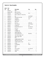
Page 24: ...24 19 38 DRUM SANDER OWNER S MANUAL Technical Specifications Head Assembly ...
Page 28: ...28 19 38 DRUM SANDER OWNER S MANUAL Technical Specifications Conveyor and Motor Diagram ...
Page 32: ...32 NOTES ...