background image

32

SUPERIOR

®

E

n

g

li

s

h

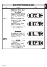
ROOM TEMPERATURE SENSOR

Sensor

Description

Display

Room sensor

Connected to the rear of the stove it constantly
monitors the temperature in the stove’s imme-
diate environs to ensure its operation in com-
plete safety.

WHEN ACTIVATED

If the sensor detaches itself momentarily

and/or accidentally from its position, the prob-

lem does not require the immediate shutdown

of the stove, which will continue to function

normally at the chosen power level.

The problem will only be indicated if the tem-

perature display has been activated, in which

case a temperaure of 0ºC will be shown.

OK

SET

GRUPPO

PIAZZETTA

1

2

3

4

5

6

AL. F

SET

AL. C

OK

SET

GRUPPO

PIAZZETTA

1

2

3

4

5

6

AL. F

SET

AL. C

WHAT TO DO

Restore the sensor to its proper position;

If the temperature display has been activated

this will once again be shown.

OK

SET

GRUPPO

PIAZZETTA

1

2

3

4

5

6

AL. F

SET

AL. C

DT2040019-00

Example of display if temperature display is activated:

Example of display if time display is activated:

6.7

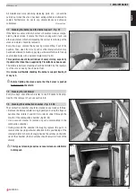
Opening the door

During operation the door must remain closed. It is to be opened only when the stove has shut down and cooled for the carrying out

of maintenance.

6.8

Removing the ash

The ash drawer must be emptied regularly. The ashes must never reach the level of the burner’s supporting arm.

The ashes must be put in a metal container with a sealable lid. Until the ashes are definitively extinguished, the container must be placed

on a non-combustible surface or on the ground and be kept well away from combustible material.

Ashes can conceal burning embers for long periods!!!

Summary of Contents for MIRELLA

Page 1: ...INSTRUCTIONS FOR INSTALLATION USE AND MAINTENANCE Pellet Stove MIRELLA SUPERIOR The instruction manual is an integral part of the product ...

Page 2: ...t the floor where the product is to be installed is exactly level To help correct potential unevenness and irregularities a sheet of adhesive fibreglass accompanies the product Do not block the electrical socket it should be close to the unit but accessible Connect the pellet stove to the electricity supply only after it has been connected by an expert to the flue system The plug at the end of the...

Page 3: ...sor 16 DT2010078 00 5 2 Installing the external thermostat 17 DT2010079 00 6 0 Use 17 DT2010080 01 6 1 Control panel 18 DT2010081 00 6 2 Startup 18 DT2010082 00 6 3 Startup and normal operation 19 DT2010083 01 6 4 Remote control 23 DT2010084 00 6 5 Timer 23 DT2010085 00 6 6 Safety features 29 DT2010086 00 6 7 Opening the door 32 DT2010087 01 6 8 Removing the ash 32 DT2010049 00 7 0 Maintenance 33 ...

Page 4: ... DISTANZE DI SICUREZZA RACCORDO CON ISPEZIONE 1 0 GENERAL RULES DT2010216 02 DT2030321 00 Ensure that the installation of your product conforms to all the following instructions Fig 1 CHIMNEY STACK SINGLE FLUEWAY OR CHIMNEY FLUE SYSTEM SOOT INSPECTION FRESH AIR INTAKE MINIMUM SAFETY DISTANCES CAPACITY LOAD OF THE FLOOR END ELBOW WITH INSPECTION WINDOW ...

Page 5: ...st 20mm and a maximum ratio between the sides of 1 5 Fig 4 The walls must be smooth if possible and without narrowing Bends must be regular and without discontinuity Fig 3 4 5 It is forbidden to make fixed or mobile apertures on the flue pipe to connect appliances other than the one to which it is already connected It is forbidden to pass other air ducts or service pipes inside the flue pipe howev...

Page 6: ...gtotheangle of inclination of the roof and it is therefore necessary to adopt the minimum heights shown in Fig 10 Example Check the slope of the roof column α and the anticipated distance of the chimney stack from the axis of the ridge column A if the distance is greater than A lthe height of the chimney stack may be read in column H if the distance is less than A the chimney stack must rise above...

Page 7: ...in a location which allows safe and convenient use as well as easy maintenance If the product being installed requires an electrical socket the room must also be provided with an earthed power supply in accordance with current regulations The installation of a wood burning appliance in a bedroom bath or shower room or in any room where another heating system not equipped with its own air supply fi...

Page 8: ...n multiplied by a coefficient which depends on the degree of insulation of the building that is on internal and external factors of the dwelling a Internal factors type of window and door frames thickness of the insulation and walls type of building materials presence of stairwells walls with extensive glazing high ceilings position of the rooms to be heated in relation to other adjacent heated or...

Page 9: ...lue must be completely airtight and correctly instal led to ensure both trouble free operation and user safety The construction of the exhaust system must be undertaken by spe cialised personnel or firms as outlined in the following pages Installation of the flue should be completed in such a way as to gua rantee that periodic cleaning can be carried out without dismantling the entire system Pipes...

Page 10: ...mum of one 90 bend is used and bearing in mind that a 90 bend can be replaced by one meter of pipe the maximum length of the section will be 4 5m 1m 1m 6 5m Where 100mm diameter pipe must be used connect it to the stove s exhaust outlet with a 80mm T connector then use a 80mm 100mm adaptor not supplied by Piazzetta Fig 19 T connector The use of this type of connector must allow for the collection ...

Page 11: ...terials wooden veneers beams or ceilings etc See figures 17 18 If the connector has to pass through partitions or walls constructed from inflammable or heat sensitive materials or through weight bea ring walls you must introduce an insulated barrier equal to or greater than 10cm around the con nector using a mineral based insulating material rock wool ceramic fibre with a nominal density greater t...

Page 12: ...l regulations When a flue pipe passes through a wall or a ceiling special installation methods must be applied protection thermal insulation distances from heat sensitive materials etc See the paragraph Connection to the flueway It is also recommended that all elements made of combustible or inflammable material such as beams wooden furniture curtaining flammable liquids etc be kept outside the he...

Page 13: ...ELLA Hourly fuel consumption max min kg h 1 4 0 75 Nominal thermal power max min kW 5 5 2 5 Efficiency 80 Draught when connected to chimney Pa 10 15 Fuel tank capacity kg l 15 23 Electrical power supply V 230 Frequenz Hz 50 Maximum power rating W 320 Power rating max min W 110 70 Exhaust outlet diameter cm Ø 8 Fresh air intake with minimum useful section cm2 100 Weight with majolica kg 85 Packing ...

Page 14: ...Serial number DT2030624 00 DT2030072 00 EXTERNAL THERMOSTAT Smoke fan Capacitor PILOT LIGHT F N SMOKE SMOKE POINTS POINTS PILOT LIGHT PILOT LIGHT FUEL LOADING CHUTE FUEL LOADING CHUTE AL 2 AL 1 N Fuel loading chute 80 1 P 2 180 1 P 2 THERMOSTATS G N L POWER THERMOELEMENT ABGASE SMOKE SENSOR ROOM SENSOR Room fan LN FAN 2 Brown Light blue Blue Black Brown Blue Red Black Black Light blue Light blue B...

Page 15: ...ed in their production Since the pellet s characteristics and quality affect to a consider ably degree the stove s performance productivity and proper functioning we recommend that you USE high quality pellets Gruppo Piazzetta S p A has tested and programmed its stoves and can promise optimum performance and trouble free functioning using pellets with these specific characteristics Material wood L...

Page 16: ...ting is indicated in the section technical character istics and data in this manual According to law the installation must be earthed and include a differential switch Ensure that in its normal position the power cable does not come into contact with any heated parts Ensure that the electrical socket is accessible after the stove s installation At the same time as installing the stove it is necess...

Page 17: ...the stove while it is in use MINIMUM 100 cm from the front panel While in use the door must remain closed and the glass must be present and intact 5 2 Installing the external thermostat Fig 24 26 27 28 To connect the external thermostat use cable type 2x0 5mm 2 stopped with a PG7 connector to be inserted in the appropriate socket in the rear panel fig 24 This operation should be carried out by aut...

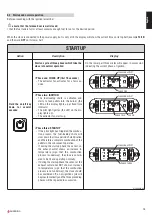
Page 18: ... when data from the remote control is received AL F AL C SET OK 3 SET 1 2 5 6 4 GRUPPO PIAZZETTA Programming The LED lights up when programming is in progress AL F AL C SET OK 3 SET 1 2 5 6 4 GRUPPO PIAZZETTA Fuel loading The LED lights up when the automatic fuel loading spiral chute is in use AL F AL C SET OK 3 SET 1 2 5 6 4 GRUPPO PIAZZETTA Pilot light The LED lights up when the pilot light is o...

Page 19: ...ED on the display lights up at fixed time intervals The pilot light ignites the LED on the dis play lights up The extractor fan starts up OK SET GRUPPO PIAZZETTA 1 2 3 4 5 6 AL F SET FLASHING SCRIPT PHASE TWO AL C LED ON Phase three STARTUP If the pilot light has triggered the combus tion process the fuel loading chute will slow down to allow a period of stabilisation and therefore a complete comb...

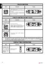
Page 20: ... C DT2040006 00 FAILED IGNITION WHAT TO DO Action Description Display 4 The alarm should stop Verify the cause of the failed ignition Always remove any fuel in the burner before starting a new ignition process OK SET GRUPPO PIAZZETTA 1 2 3 4 5 6 AL F SET AL C 4 The startup up process will be activated as detailed above If the appliance does not ignite properly the main cause could be either insuff...

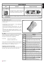
Page 21: ...A 1 2 3 4 5 6 AL F SET AL C During normal operation the burner s automat ic cleaning system will activate periodically the frequency varying according to the settings pre programmed by Gruppo Piazzetta person nel This operation removes ash deposits and other buildups which impede the correct func tioning of the stove OK SET GRUPPO PIAZZETTA 1 2 3 4 5 6 AL F SET AL C Example Example DT2040005 00 IN...

Page 22: ...perature reaches the pro grammed value the corresponding LED lights up the stove runs at minimum power even if the input power level is shown on the display OK SET GRUPPO PIAZZETTA 1 2 3 4 5 6 AL F SET FLASHING SCRIPT LED ON AL C INTERNAL THERMOSTAT setting desired room temperature Action Description Display To change the tem perature setting press key 3 SET Then press key 1 to increase the temper...

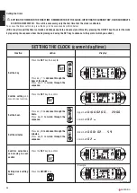
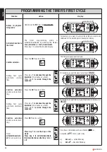
Page 23: ...programmed For example Cycle one from 6 until 9 am Cycle two from 8 30 until 11 pm The two cycles can be activated or deactivated on each of the days of the week eg if you want the stove to be lit from 6 until 9 on Monday Tuesday but not on Wednesday and so on Programming codes and relative functions During programming certain codes will appear in the lower part of the display These represent the ...

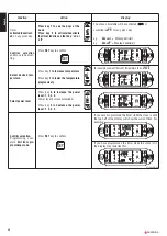
Page 24: ...y then key 6 Press key 1 to advance through the days of the week Press key 2 to return through the sequence OK SET GRUPPO PIAZZETTA 1 2 3 4 5 6 AL F SET AL C Confirm setting and move to next section Press the SET key to confirm OK SET GRUPPO PIAZZETTA 1 2 3 4 5 6 AL F SET AL C Set the hour Press key 1 to advance through the hours Press key 2 to return through the sequence Upper half 01 00 02 00 23...

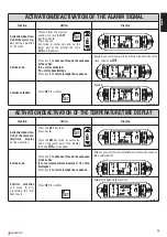
Page 25: ...e during operation of the stove select code 09 Example ACTIVATION DEACTIVATION OF THE TEMPERATURE TIME DISPLAY Function Action Display Activation deactiva tion of the tempera ture time display during operation Press the SET key then press key 6 Press the SET key twice in succession and on the lower part of the display the code 03u will appear OK SET GRUPPO PIAZZETTA 1 2 3 4 5 6 AL F SET AL C Set t...

Page 26: ... ting Press the SET key to confirm OK SET GRUPPO PIAZZETTA 1 2 3 4 5 6 AL F SET AL C Setting first cycle automatic shutdown time Press key 1 to advance through the timetable 10 minutes at a time Press key 2 to return through the sequence OK SET GRUPPO PIAZZETTA 1 2 3 4 5 6 AL F SET AL C Confirm selection and move to next set ting Press SET key to confirm OK SET GRUPPO PIAZZETTA 1 2 3 4 5 6 AL F SE...

Page 27: ...perature to be 20 C 1 2 5 6 PROGRAMMING THE TIMER S SECOND CYCLE Function Action Display Setting second cycle automatic startup time Press key 1 to advance through the timetable 10 minutes at a time Press key 2 to return through the sequence OK SET GRUPPO PIAZZETTA 1 2 3 4 5 6 AL F SET AL C Confirm selection and move to next set ting Press the SET key to confirm OK SET GRUPPO PIAZZETTA 1 2 3 4 5 6...

Page 28: ...ure progressively OK SET GRUPPO PIAZZETTA 1 2 3 4 5 6 AL F SET AL C Select power level Press key 6 to increase the power level 1 2 3 4 Power level 2 is recommended Press key 5 to decrease the power level 1 2 3 4 OK SET GRUPPO PIAZZETTA 1 2 3 4 5 6 AL F SET AL C Confirm selection Programming com plete Exit from pro gramming mode Press SET key to confirm OK SET GRUPPO PIAZZETTA 1 2 3 4 5 6 AL F SET ...

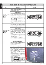
Page 29: ...let it s function is to check the pressure inside the exhaust outlet allowing operation of the stove in complete safety WHEN ACTIVATED If ideal operation conditions in the exhaust out let become altered incorrect installation blockages or impediments in the flue poor maintenance unfavourable weather conditions such as persistent wind etc the sensor will stop the power supply to the fuel loading ch...

Page 30: ...ll stop the power supply to the fuel loading chute blocking the supply of fuel to the burner and starting the shutdown process In the upper part of the display the message Hot tEMP will appear and in the lower half AL 2 The LED beside AL C will light up After 60 seconds the alarm will sound if acti vated OK SET GRUPPO PIAZZETTA 1 2 3 4 6 AL F SET FLASHING SCRIPT LED ON AL C WHAT TO DO IN BOTH CASE...

Page 31: ...has stopped Check for and remove whatever has triggered the alarm After having cleaned the burner restart the stove by pressing the ON OFF key 4 OK SET GRUPPO PIAZZETTA 1 2 3 4 5 6 AL F SET AL C Smoke sensor Disconnected WHEN ACTIVATED If the sensor becomes detached momentarily and or accidentally from its position or if it is not connected properly to the electronic board The problem will be indi...

Page 32: ... F SET AL C WHAT TO DO Restore the sensor to its proper position If the temperature display has been activated this will once again be shown OK SET GRUPPO PIAZZETTA 1 2 3 4 5 6 AL F SET AL C DT2040019 00 Example of display if temperature display is activated Example of display if time display is activated 6 7 Opening the door During operation the door must remain closed It is to be opened only whe...

Page 33: ... dictated by the regulari ty of the stove s use by the choice of fuel It is always worthwhile checking the burner s support freeing it of any ash Before lighting the stove ensure that the burner is pushed back towards the shield 7 2 Cleaning the ash drawer Every two days check the ash drawer to see if it needs to be emp tied For the removal of ash see section 5 8 7 3 Cleaning the combustion chambe...

Page 34: ...e cleaned with a soft dry cloth before using even delicate detergents and a damp cloth DO NOT SOAK THE CERAMIC AND NEVER USE COLD WATER WHEN IT IS STILL HOT THE THERMAL SHOCK COULD BREAK IT 7 7 Cleaning the metal parts Clean the metal parts with a soft damp cloth NEVER CLEAN METALLIC PARTS USING ALCOHOLS SOLVENTS PETROLEUM BASED AGENTS ACETONES OR OTHER GREASE REMOVING SUBSTANCES In the case of su...

Page 35: ... 11 Cleaning the fans Any cleaning or maintenance operation must be carried out after the CURRENT HAS BEEN SWITCHED OFF The stove is equipped with fans smoke extractor and heating positioned low down at the rear Any buildup of dust or ash on the blades can unbalance them resulting in noise during operation Therefore it is necessary to have the fans cleaned annually Since such an operation involves...

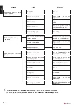
Page 36: ...f problem persists call an electrician Defective control panel Replace the control panel use only original spares Defective flat cable Replace flat cable use only original spares Defective electronic board Replace electronic board use only original spares External pressure reader warning AL 1 NO DEPR Blocked flue Check and clean the flue Broken smoke extractor Replace the motor use only original s...

Page 37: ...nual reset pressure reader warning AL 2 Hot tEMP Blocked flue Check and clean the flue Defective thermostat Replace thermostat use only original spares Badly positioned thermostat Check position of sensor Defective electronic board Replace electronic board use only original spares Temporary power cut Manually reset the pressure readers see AL 2 Defective fan Check the fan replace if necessary use ...

Page 38: ...only original spares Badly positioned sensor Check connections Stove runs for 9 10 minutes then goes out The heat sensor is blocked Retry and if problem persists con tact an authorised technician Exhaust fumes have not reached required temperature Retry and if problem persists contact an authorised technician Heat sensor badly connected Check cabling and connections Blocked flue Clean flue Failed ...

Page 39: ...uent amendments and that all the following standards have been applied EN 55014 1 1993 EN 55014 1 A1 1997 EN 55014 1 A2 1999 EN 61000 3 2 1995 EN 61000 3 2 A1 1998 EN 61000 3 2 A2 1998 EN 61000 3 2 A14 2000 EN 61000 3 3 1995 EN 55014 2 1997 EN 60335 1 1994 EN 60335 1 Ec 1995 EN 60335 1 A11 1995 EN 60335 1 A1 1996 EN 60335 1 A12 1996 EN 60335 1 A13 1998 EN 60335 1 A14 1998 EN 60335 1 A15 2000 EN 50...

Page 40: ... p A Technical Department Cod H07010500 DT2000009 Rev 02 04 2005 Via Montello 22 I 31010 Casella d Asolo TV Italia Tel 39 04235271 Fax 39 042355178 http www superiorcaminetti it e mail infopiazzetta piazzetta it SUPERIOR ...

Reviews: