5
SECTION 1 - ASSEMBLY
Mechanical Assembly
1.
Before starting the assembly of the robot, be sure to follow the instructions to remove the brake from the back of the motors. The
brake is engaged by default. Running the motor with the brake on will damage it beyond repair.
2.
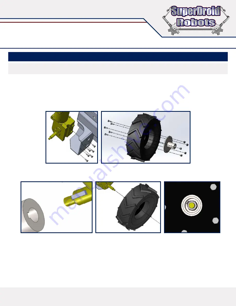
Once the brake is removed, remove the six socket head screws that hold the outer clamping plate to the motor. This plate will not
be used and can be discarded. Keep the socket head screws that were removed and use them to mount the motor to the chassis.
Use Loctite to keep the screws from vibrating loose. See
Figure 2
.
3.
Let air out of the pneumatic wheels so that they are easier to manipulate. Take care not to pinch the inner tube when bolting to the
hub. After the wheel is bolted in place, fill the tire with air to match the specifications on the side wall of the tire. See
Figure 3
.
Figure 2
Figure 3
Figure 4A
NOTE
Your robot may come in a crate or carry case. As you unpack your robot, note how everything fits so you can store your platform.
Figure 4B
Figure 4C
4.
Align the key slot on the hub with the key stock on the motor shaft. Slide components together and secure with the provided M10
nut. See
Figure 4A, Figure 4B,
and
Figure 4C
.


