

Read the owners manual carefully before installing the BG!
Characteristics
Auto 12V/24V detection
Handling of high currents
Latching relay
Very low stand-by current
Purpose
The Securing of a LiFePO4 (lithium iron phosphate or LFP) battery against under- and overvoltage with the lowest possible stand-by current.
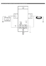
Installation
1.
Connect the consumer equipment to T2.
2 (optional).
Connect a switch to the remote input (see wiring diagram for details).
3 (optional).
Connect a light-source to the status output.
4.
Connect the positive terminal of the battery to T1.
5.
Connect the positive terminal of the battery to A1.
6.
Connect the minus connector of the BDB-250 via a fuse to the negative terminal of the battery.
Warning:
The product should only be fitted by qualified personal who are aware of the requirements for working with high battery voltages.
The use of faulty connection material or wires with insufficient diameter can result in damaged equipment.
A short between the positive and negative terminal of the battery can do serious damage to your system.
Operation
All the mentioned voltages, are applicable to a 12V system. For a complete list of all voltages for both the 12V and the 24V system, the table below can be
consulted.
Boot
Before the BDB-250 becomes operational, it has to determine if a 12V or a 24V system is connected. This means that after connecting the BDB-250, the first
thing it does is wait a second before doing anything else. After this, if the input voltage is above 10.0V below and 15.4V, the relay will close. If these conditions
are not met, the relay will open.
High voltage
If the input voltage rises above 15.0V, the LED will start blinking to indicate a detected overvoltage. This will continue for
90 seconds after which the relay will be opened and the LED will turn off.
When the voltage rises above 15.4V, the entire “warning” process will be skipped and the relay will switch off immediately.
Low voltage
If the input voltage drops below 10.0V, the LED will blink to indicate an under-voltage situation. This will continue for 90
seconds after which the relay will be opened and the LED will turn off.
Reset
When the BDB-250 is switched off and the voltage returns between 11.0V and 14.0V, there are two ways to re-activated
it.
If the user has chosen the automatic reset function, the relay of the BDB-250 will be activated directly after a “correct”
voltage has been measured. However, when the manual reset function has been programmed, the user has to reset the
BDB-250 by hand. This is done by pressing the build-in switch. If an external switch is connected to the remote input, this can also be used to reset it manually.
The manner in which the BDB-250 will be reset is programmable by the user. The manner in which this is done can be found under “Programming”
Programming
The user can choose if the BDB-250 is reset manually of automatically. This is done by pressing the programming button and holding
it down until the LED flashes. This indicates that the BDB-250 is in programming mode. At this point the button must be released.
When the button is pressed once now, the automatic reset function is selected. If the user presses the button twice, the manual reset
is selected.
Approximately 4 seconds after the last time the button is pressed, the LED will blink to show the programmed reset function. (e.g.: If
position 2 – manual reset – is selected, the LED will blink twice.)
Technical specifications
Dimensions
Weight
370 g
Dimensions
WxHxD
82x57x120 mm
Mounting holes
Ø
5 mm
Terminal strips
WxHxD
Ø
19x2x18 mm
8 mm
Electrical data
Autodetect 12V or 24V system
12V mode
24V mode
8V to 20V
20V to 35V
Current consumption
Active
Passive
3mA
2mA
Input surge current (100ms)
12V mode
24V mode
2.6A
5.0A
Switch current
Continues
Peak
250A
1500A
reset type
1
2
prog nr.
automatic
manual
12V
24V
direct
8.0V
16.0V
alarm
10.0V
20.0V
reset
11.0V
22.0V
Over voltage
direct
15.4V
30.8V
alarm
15.0V
30.0V
reset
14.0V
28.0V
system
Under voltage


