


CrossFire HP – All-Digital Transport System
User Guide
© SUNWAVE COMMUNICATIONS LIMITED 2015
32
Revision 05
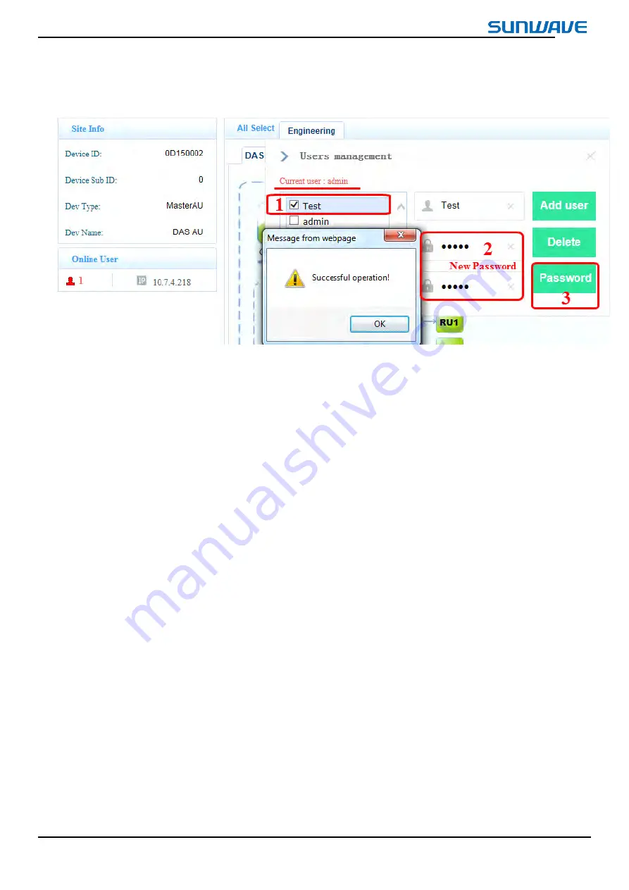
c)
Click
Password
Password
Password
Password
button.
Figure
Figure
Figure
Figure 2
222---- 17
17
17
17 Change
Change
Change
Change Password
Password
Password
Password
2.3.4.
2.3.4.
2.3.4.
2.3.4.
Displaying
Displaying
Displaying
Displaying the
the
the
the System
System
System
System Topology
Topology
Topology
Topology
To display the system topology:
1. Log in to the WebOMT.
2. Select the main
Engineering
Engineering
Engineering
Engineering
tab.
3. Select the
DAS
DAS
DAS
DAS Topo
Topo
Topo
Topo
tab.
4. Select
Query
Query
Query
Query all
all
all
all
.
Figure 2- 18 shows the system topology display. If networking is successful, arrows will be displayed for the six
optical ports behind the Master AU (for example, see the green “EU1” icon in Figure 2- 18), which means that there are
connected devices corresponding to the optical port. Click the arrow to extend the topology for this port.


