background image

IOM-WR-TapeMat 1526 

20 of 32

Phase 5 - Control Installation

STEP 5.1: 

Install the Controls

If it has not already been done, install an electrical box for the SunStat thermostat and SunStat 

Relay. See Step 2.2 for details.

STEP 5.2

Read and follow the instructions included with the SunStat thermostat and SunStat Relay for 

complete connection instructions, requirements, and mounting.

STEP 5.3

Make any final connections to the circuit breaker or branch circuit source.

Most laminate and wood floor manufacturers specify their flooring should not be subjected to 

temperatures over 82° to 84°F (27° to 28°C). Check with the flooring dealer or manufacturer 

and set the thermostat Floor Limit temperature appropriately.

Refer to the installation sheets provided with the controls for proper setting. The system 

should now operate as designed. 

Please leave this instruction manual, SunStat Control 

instructions, and copies of photos of the installed heating system with the end user.

CKT#

CKT#

CKT#

Radiant Floor Heating Mat

Warning - Risk of electric shock


 Electric wiring and heating panels 

contained below the floor. Do not 

penetrate floor with nails, screws,  

or similar devices

Nappe de chauffage de sol

Avertissement: Rique de choc électrique


 Câblage électrique et nappes de chauffage 

dans le sol. Ne pas enfoncer de clous, vis 

ou autes éléments d’assemblage similaires.

Tapete radiante para calefaccion de pisos

Precaución: Riesgo de electrocución


 El piso contiene cables eléctricos y paneles 

calafactores. No insertar clavos, tornillos ni 

dispositivos similares.

STEP 5.4

System Start Up

After all controls are installed, do not energize the system, except to briefly test operation of 

all components (no longer than 10 minutes). 

Do not put the system into full operation until 

the tile or flooring installer verifies all cement materials are fully cured (typically two to 

four weeks)

. See mortar manufacturer’s instructions for recommended curing time.

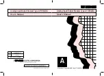
Place this warning label (provided with 

the product) on the electrical panel and 

indicate the circuit breaker number that 

supplies the radiant heating. Also, place 

the label indicating “Radiant Floor Heating” 

on the control.

Make sure 120 VAC is supplied to 120 VAC mats and 240 VAC is supplied to 240 VAC mats. 

Otherwise, dangerous overheating and possible fire hazard can result.

Summary of Contents for TapeMat C12 series

Page 1: ...are local codes may require this product and or the thermostatic control to be installed or connected by an electrician Please leave this manual with the end user Includes Custom TapeMat and ShowerMat...

Page 2: ...6 Application Indoor floor heating only X on the nameplate label indicates CUL Listing for this application Suitable for installation in a shower area see Step 3 10 for restrictions W on the nameplate...

Page 3: ...or or moderate injury This symbol identifies practices actions or failure to act which could result in property damage or damage to the equipment Table of Contents Important Safety Information 3 Phase...

Page 4: ...g NEVER forget to install the floor sensor included with the thermostat NEVER install TapeMat in any walls or over walls or partitions that extend to the ceiling NEVER install mats under cabinets or o...

Page 5: ...product appears to be damaged the factory must be called before proceeding with the installation Before installing TapeMat make sure to fully inspect the products and carefully plan the site Items Nee...

Page 6: ...40 2 x 20 12002024 4 0 25 32 45 2 x 22 6 12002224 4 5 22 28 50 2 x 25 12002524 5 0 20 26 60 2 x 30 12003024 6 0 17 21 70 2 x 35 12003524 7 0 14 18 80 2 x 40 12004024 8 0 12 16 90 2 x 45 12004524 9 0 1...

Page 7: ...9 C 8 000 ohms Table 3 Floor Sensor Resistance Values STEP 1 3 Use a digital multi meter set to the 200 or 2000 2k range to measure the resistance between the conductors of the mat power leads Record...

Page 8: ...0VAC Sensor wire AFTER MAT AND SENSOR ARE FASTENED TO FLOOR OHMS Mat black to white black to blue for 240VAC Mat black to ground Mat white to ground blue to ground for 240VAC Sensor wire AFTER FLOOR C...

Page 9: ...ons included with the SunStat for complete information on location and wiring The thermostat must be located at least 4 feet 1 2 meters away from shower openings to avoid being exposed to water or tou...

Page 10: ...m plate up to the electrical box For multiple power leads multiple mats install 3 4 conduit Thermostat Sensor The SunStat Control sensor can be installed with or without electrical conduit depending o...

Page 11: ...to reach the control location it may be possible to cut the mat mesh and pull loose the length of heating wire needed It is acceptable to run the power lead several feet in the floor area and embed i...

Page 12: ...6 from a toilet wax ring It may be installed closer to walls if necessary but make sure the heating wire will not be located underneath finish trim Install in line with vanity and counter areas Instal...

Page 13: ...Roll over Installing in front of cabinets and toilets Install mat right up to the face of the cabinet as shown above Mat can be installed under tile to within 6 from the wax ring and can slightly unde...

Page 14: ...tar DO NOT staple or apply tape over the heating wire Damage can result DO NOT use nails duct tape other types of tape or other unapproved fasteners to hold the heating wire or mesh in place Damage ca...

Page 15: ...t 1 into the mat area halfway between the heating wires and secure it using hot glue Do not cross the heating wires It may be necessary to chisel a small section of the subfloor to accommodate the sen...

Page 16: ...run the heating wire through a non masonry curb causing it to overheat 7 Embed mats in mortar and install only under tile stone brick or other masonry surface per this instruction manual 8 Never begin...

Page 17: ...see their web site at www tile assn com When installing floor coverings other than tile or stone follow industry and or manufacturer s recommendations Ensure the mat is first covered with a layer of s...

Page 18: ...ick according to manufacturer s specifications Fully embed the heating wire and splices so that no portion of these show Install floor covering after the mortar has cured Special Precautions Isolation...

Page 19: ...rack isolation membrane Insulating barrier TapeMat Thin set or self leveling mortar bed Insulation per International Residential Code Chapter 11 Insulation per International Residential Code Chapter 1...

Page 20: ...ing and heating panels contained below the floor Do not penetrate floor with nails screws or similar devices Nappe de chauffage de sol Avertissement Rique de choc lectrique C blage lectrique et nappes...

Page 21: ...istance between two heating wires Electrical box Single gang Mud Ring if required Electrical conduit Sensor wire Mat power lead Mat Mesh Thin set thick set thin slab or self leveling mortar bed Tile s...

Page 22: ...IOM WR TapeMat 1526 22 of 32 Appendix 90 Turn 90 Flip Roll over Turn 180 or Back to Back Turn Fill in Technique Types of turns...

Page 23: ...23 of 32 2015 Watts Water Technologies Step by step layout for a typical bathroom 1 2 3 4 5 6 7 8...

Page 24: ...One mat Toilet Shower Bath Tub Closet Vanity Control Install 4 6 from walls Install mats right up to the face of the cabinet The heat only conducts about 1 1 2 from the wire Install mats 6 away from...

Page 25: ...Three mats Small bath layout One mat Front Entryway Doorway Doorway Control Sink Bath Tub Install mats right up to the face of the vanity The heat transfers only about 1 1 2 from the wire Control Inst...

Page 26: ...ring approximately 20 from back wall Fill in triangular areas by removing wire from mat and securing with hot glue Toilet Control Do not begin the mat inside the shower area The controls should NEVER...

Page 27: ...local inspector or the authority having jurisdiction Never install the mat in shower walls or any other walls Shower installation detail Locate power lead and factory connection to heating wire at lea...

Page 28: ...m any electrical work unless qualified to do so Work should be done with great care and with power turned off to the circuit being worked on Follow all local building and electrical codes The thermost...

Page 29: ...If it trips again check for a short circuit in the mat as detailed earlier in this manual If mat is damaged record resistance between all wires and contact the manufacturer If mat is not damaged repla...

Page 30: ...to the control Also see Sensor is loose or broken above Loose connection s on line side and or load side of control Remove and reinstall the wire nuts at each connection Make sure the wire nuts are t...

Page 31: ...eding with the installation or proposed repair THECOMPANIESDISCLAIMANYWARRANTYNOTPROVIDEDHEREIN INCLUDING ANY IMPLIED WARRANTY OF MERCHANTABILITY OR IMPLIED WARRANTY OF FITNESS FOR A PARTICULAR PURPOS...

Page 32: ...RQA 8 4 0 2 1 3 1 1 3 3 1 5 SunTouch Customer Support USA Toll free 888 432 8932 USA Fax 417 831 4067 Canada Toll free 888 208 8927 Canada Fax 905 332 7068 Latin America Tel 52 81 1001 8600 Latin Amer...

Reviews: