TWN4 can be configured as CDC / Virtual COM port and can then be accessed like any serial interface. It
provides all necessary commands for the NFC interface, specifically to:
1.Read data from configuration memory and write data to configuration memory
2.Authenticate the user (to allow read / write of protected memory) via 32 bit PIN
NFC functionality is also available in certain Android smart phones and tablets. NXP provides a SW framework
that can be used with Android devices and can advise regarding suitable tablets and smart phones.
NFC communication distance is for security reasons set to require direct contact between reader and switches
based on SR-SBP2801-BLE-E.
6.2 NFC interface functions
For a detailed description about the NFC functionality, please refer to the ISO/IEC 14443 standard.
For specific implementation aspects related to the NXP implementation in NT3H2111,
please refer to the NXP documentation which at the time of writing was available under this link:
https://www.nxp.com/docs/en/data-sheet/NT3H2111_2211.pdf
The following chapters summarize the different functions for reference purposes.
6.2.1 NFC interface state machine
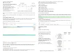
Figure 22 below shows the overall state machine of the NFC interface.
Figure 22 – NFC interface state machine
6.2.2 IDLE state
IDLE is the waiting state after a Power-On Reset (POR), i.e. after the NFC tag has been introduced into the
magnetic field of the NFC reader.
The NFC tag exits the IDLE state towards the READY 1 state when either a REQA or a WUPA command is
received from the NFC reader. REQA and WUPA commands are transmitted by the NFC reader to determine
whether any cards are present within its working range.
Any other data received by the NFC tag while in IDLE state is discarded and the NFC tag will remain in IDLE
state.
6.2.3 READY 1 state
READY 1 is the first UID resolving state where the NFC tag resolves the first 3 bytes of the
7 byte UID using the ANTICOLLISION or SELECT commands for cascade level 1.
READY 1 state is exited after the SELECT command from cascade level 1 with the matching complete first part
of the UID has been executed. The NFC tag then proceeds into READY 2 state where the second part of the
UID is resolved.
6.2.4 READY 2 state
READY 2 is the second UID resolving state where the NFC tag resolves the remaining 4 bytes of the 7 byte UID
using the ANTICOLLISION or SELECT commands for cascade level 2.
READY 2 state is exited after the SELECT command from cascade level 2 with the matching complete part of
the UID has been executed. The NFC tag then proceeds into ACTIVE state where the application-related
commands can be executed.
6.2.5 ACTIVE state
ACTIVE state enables read and write accesses to unprotected memory.
If access to protected memory is required, then the tag can transition from the ACTIVE state to
AUTHENTICATED state by executing the PWD_AUTH command in conjunction with the correct 32 bit
password.
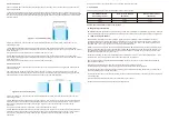
Figure 23 – NFC read command sequence
6.2.7 Write command
The WRITE command requires a start page
address and returns writes 4 bytes of data into
that page.
Figure 24 below shows the read command
sequence.
Figure 24 – NFC write command sequence
6.2.6 Read command
The READ command requires a start page
address, and returns the 16 bytes of four
NFC tag pages (where each page is 4 byte in
size).
For example, if the specified address is 03h
then pages 03h, 04h, 05h, 06h are returned.
Spe- cial conditions apply if the READ
command address is near the end of the
accessible
memory area.
Figure 23 below shows the read command
sequence.


