Sungrow SC50HV Quick Installation Manual Download Page 12


12 


3-7  Battery Connection 

Step 1 

Rotate  the  BAT 

switch  to  the  “OFF” 

position. 

Step 2 

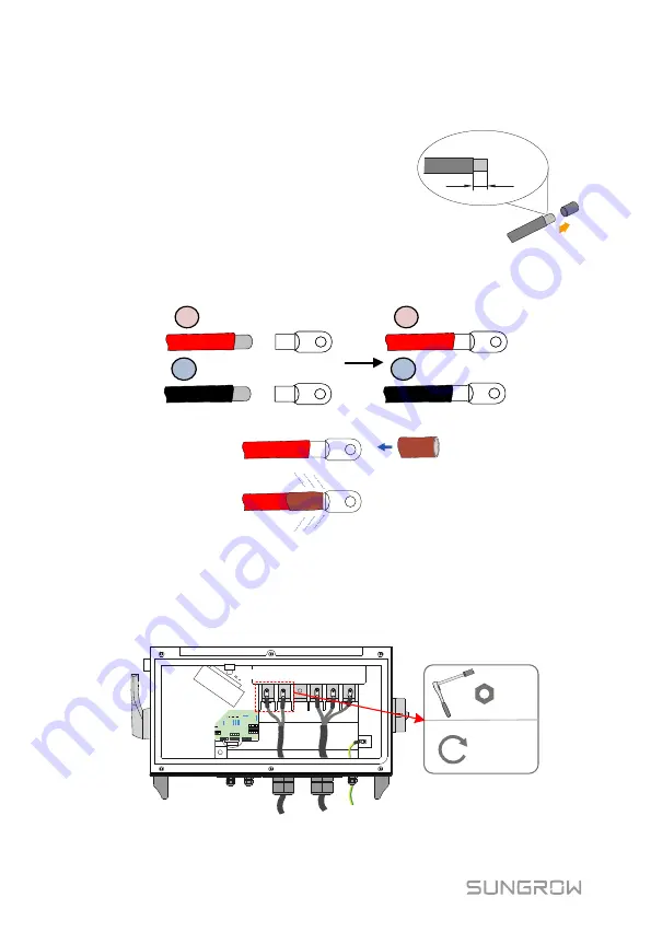
Strip the insulation layer of the DC cable to 
proper  length  according  to  the  DC  cable 
specification. 


Step 3 

Insert the end of the DC cable to the cable socket that matches with the 
M10 bolt and tighten it with the proper tool. 

+

-

+

-


Step 4 

Install the heat-shrinkable tubing, shrink the tubing with hot air blower. 

.


Step 5 

Loosen the swivel nut of the gland terminal (Marked as 

“BAT. Input”) and 

select  an  appropriate  seal  according  to  cable  outer  diameter.  Lead  the 
cable through the swivel nut and seal successively. 

Step 6 

Connect  the  positive  and  negative  polarity  of  the  DC  cable  to  the 
corresponding positive and negative cable connection terminals. 

M10

34~40 N.m

BAT+

BAT-


Summary of Contents for SC50HV

Page 1: ...al can be downloaded by visiting the website at http support sungrowpower com or it can be obtained by scanning the QR code on the side of the equipment or the back cover of the Quick Guidance Any vio...

Page 2: ...Backplate It is used for mounting PCS onto the wall C Documents Documents include quality certificate packing list product test report and quick user manual D Fastener set Six units It is used for fas...

Page 3: ...wall materials material Flammable wall Flammable material or gas near theinstallation Requirement for installation height Ground Requirement for installation angle Requirement for installation space T...

Page 4: ...s following procedures Step 1Remove the backplate and fasteners from the packaging Step 2Place the backplate to the chosen metal frame and adjust it to proper position and height Step 3Mark the positi...

Page 5: ...make sure they match perfectly Step 2After putting the converter on the backplate secure the converter to the backplate with two M4 16 screws fix screw hole has its own nut Mount the PCS No Name Descr...

Page 6: ...tions have completed 3 1 Open the Connection Cabinet Loose the six screws on the front cover of the connection cabinet and remove the front cover to see the internal layout of the connection cabinet 2...

Page 7: ...75 5mm 11 PE cable gland For PE cable connection 3 2 Cables Selection Second PE Cable The cross sectional area of the second PE cable shall be exactly the same with that of the PE cable of the AC cabl...

Page 8: ...ct between the AC copper bar and the aluminum cable Aluminum cable Conversion terminal Directly connecting the aluminum cable to the copper bar will cause abnormal operation or even device damage 3 4...

Page 9: ...circuit breaker recommended specification 125A 690V between the PCS and the AC side Step 1Disconnect AC circuit breaker to prevent it from inadvertently reconnecting Step 2Loosen the six screws M6 16...

Page 10: ...rresponding terminals L1 L2 L3 M10 34 40 N m Pictures here are indicatively only Product in kind prevail Please avoid squeezing the cable insulation layer into the AC terminal Improper connection may...

Page 11: ...2 1 Heat shrink tubing 2 Cord end terminal Step 2Loosen the swivel nut of the gland terminal Marked as PE cable and select an appropriate seal according to cable outer diameter Lead the cable through...

Page 12: ...and tighten it with the proper tool Step 4Install the heat shrinkable tubing shrink the tubing with hot air blower Step 5Loosen the swivel nut of the gland terminal Marked as BAT Input and select an...

Page 13: ...ture and ensure long term and normal operation of the PCS 3 8 Communication Connection Step 1Thread the Network cable through communication cable gland to the configuration circuit board Step 2Strip o...

Page 14: ...revent the entry of foreign bodies or moisture and ensure long term and normal operation of the PCS Step 6Connect the communication devices Refer to other manuals and documents if there are other devi...

Page 15: ...App to establish the communication connection with the PCS through Bluetooth to set the initial parameters When the device is initialized send start instructions via the App For details please refer...

Reviews: