background image

10

4.4.1 Wall-Mounting

Mount the COM100 onto the concrete wall or metal surface according to

onsite conditions.

Avoid drilling holes in the utility pipes and/or cables attached to back of the wall!

Operation personnel should wear goggles and dust mask throughout the drilling

process to avoid dust inhalation or contact with eyes.

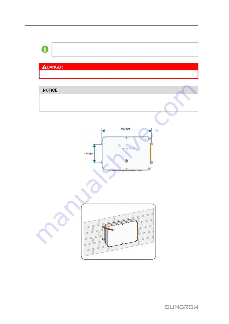
The following figure shows the installation dimensions of the COM100.

4.4.1.1 Concrete Wall

Step 1

Select an appropriate installation surface.

Step 2

Mark positions for drilling holes with a marker.

Step 3

Drill the holes with a drill according to the marks made before.

4 Mechanical Installation

User Manual

Summary of Contents for COM100D

Page 1: ...n n B Bo ox xU Us se er r M Ma an nu ua allC CO OM M1 10 00 0D D_ _E E U UE EN N V Ve er r1 12 2 2 20 02 21 10 07 7 V Ve er rs siio on n 1 1 2 2 COM100D_E UEN Ver12 202107 Version 1 2 COM100D COM100E S Sm ma ar rt t C Co om mm mu un niic ca at tiio on n B Bo ox x U Us se er r M Ma an nu ua all ...

Page 2: ......

Page 3: ...rance 6 3 3 Dimensions 6 4 Mechanical Installation 8 4 1 Unpacking and Inspection 8 4 2 Location Requirements 9 4 3 Installation Tools 9 4 4 Installation Method 9 4 4 1 Wall Mounting 10 4 4 2 Pole Mounting Optional 12 4 5 Magnetic Base Antenna Connection Optional 13 5 Electrical Connection 15 5 1 Waterproof Terminal Description 15 5 2 Internal Structure 16 5 3 Preparation Before Cable Connection 1...

Page 4: ...n Description 26 7 2 Interface Description 27 7 2 1 Digital Control Interface 27 7 2 2 Analog Control Interface 29 7 2 3 DRM Control Interface 29 8 WEB Interface 31 8 1 Running Requirements 31 8 2 Configure PC Network Parameters 31 8 3 Login Steps 31 8 4 Interface Introduction 32 9 Appendix 34 9 1 Technical Parameters 34 9 2 Dry Contact Wiring Cable 35 9 3 Quality Guarantee 35 9 4 Contact Informat...

Page 5: ...C primary node and lighting device inside Support of 4G and WLAN communication COM100E Includes the Logger1000B switch mode power supply surge protection device miniature circuit breaker MPLC switch MPLC primary node and lighting device inside Support of WLAN communication The magnetic base antenna and I O module are optional components If you want to purchase them please contact SUNGROW 1 3 Inten...

Page 6: ...ation This manual contains important safety and operational instructions that must be accurately understood and respected during the installation and maintenance of the equipment To ensure the optimum use of this manual note the following explanations of the symbols used DANGER indicates a hazard with a high level of risk which if not avoided will result in death or serious injury WARNING indicate...

Page 7: ... at the critical points in corresponding chapter All operation and electrical work must only be performed by qualified personnel B Be ef fo or re e I In ns st ta alllla at tiio on n After receiving the device please check if there is damage caused during transport Contact SUNGROW or the logistic company once any problem is detected The related operators must be familiar with the safety instruction...

Page 8: ...0 can only be performed by qualified personnel from service dept of SUNGROW or other qualified personnel End user can never maintain or replace the modules and other parts Serious personal injury or property loss may follow if otherwise Never replace the internal components of the COM100 without authorization SUNGROW shall not be held liable for any possible damage caused by ignorance of this warn...

Page 9: ...rs Smart Energy Meters and Meteo Stations Support of IV curve online diagnosis with iSolarCloud A Au ux xiilliia ar ry y m ma aiin nt te en na an nc ce e Support of batch inverter parameter setting and software upgrading Support of remote desktop function Support of grid control instruction and power factor control Support of local real time monitoring Support of automatic search and allocation of...

Page 10: ...ent 3 2 Appearance I It te em m N Na am me e D De es sc cr riip pt tiio on n A Mounting ear 4 for ease of installation B Waterproof terminal For details about the definition refer to section 5 1 Waterproof Terminal Description 3 3 Dimensions The dimensions of the COM100 are as follows 3 Product Introduction User Manual ...

Page 11: ...7 F Fiig gu ur re e 3 3 1 1 COM100 dimensions W Wiid dt th h W W H He eiig gh ht t H H D De ep pt th h D D 460mm 315mm 126mm User Manual 3 Product Introduction ...

Page 12: ...eport packing list warranty card and certificate C Cable tie 12 used for binding the cables D Hexagon bolt assembly 4 M6 x 45 used for wall mounting to fasten the device on the metal surface E Expansion bolt 4 M6 x 60 used for wall mounting to fasten the device on the concrete wall F Terminal resistor 6x120Ω Note if there are more than 15 devices connected on the RS485 bus it is recommended to con...

Page 13: ...anti moisture and anti corrosion measures 4 3 Installation Tools Installation tools include but are not limited to the following recommended ones If necessary use other auxiliary tools on site 4 4 Installation Method COM100 can be installed on a wall or mounted on a pole Be aware of the weight of the COM100 throughout the installation process Tip over or fall of the device due to inappropriate ope...

Page 14: ... should wear goggles and dust mask throughout the drilling process to avoid dust inhalation or contact with eyes The following figure shows the installation dimensions of the COM100 4 4 1 1 Concrete Wall Step 1 Select an appropriate installation surface Step 2 Mark positions for drilling holes with a marker Step 3 Drill the holes with a drill according to the marks made before 4 Mechanical Install...

Page 15: ...oles Step 5 Use the nuts flat washers and spring washers in the delivery accessories to fix COM100 on the installation surface E En nd d 4 4 1 2 Metal Surface Step 1 Select an appropriate installation surface Step 2 Mark positions for drilling holes with a marker User Manual 4 Mechanical Installation ...

Page 16: ... 4 4 2 Pole Mounting Optional COM100 can be mounted on a pole If you need to purchase this scheme contact SUNGROW who will provide the design drawings Accessories supplied with the COM100 include matching screw assembly nuts brackets clamps etc The installation procedure is as follows Step 1 Anchor the COM100 to the mounting brackets by using the screw assembly via the mounting ears as shown in th...

Page 17: ...nal COM100 has a built in antenna If COM100 is installed in a container a magnetic base antenna must be purchased to remove signal shielding Step 1 Release the 4 screws on the front side of the COM100 and open the front cover of the cabinet Step 2 Unscrew the built in antenna of COM100 User Manual 4 Mechanical Installation ...

Page 18: ...e antenna through the RF waterproof terminal and secure clockwise the nut at the end of the antenna to the corresponding terminal on the bottom of the Logger1000 Step 5 Place the sucker antenna base on a metal surface outside the container E En nd d 4 Mechanical Installation User Manual ...

Page 19: ...e A RF Reserved antenna waterproof terminal B AI DI AI DI waterproof terminal 2 х 1 1 5 mm2 Outdoor UV rated twisted pair with a shielding layer C DI DRM DI DRM waterproof terminal D RS485 1 RS485 waterproof terminal 2 х 0 75 1 5 mm2 E ETH Ethernet waterproof terminal CAT5 outdoor UV rated cable with a shielding layer F RS485 2 IOM RS485 IO waterproof terminal 2 х 0 75 1 5 mm2 Outdoor UV rated twi...

Page 20: ...tiio on n A Logger1000A or Logger1000B B I O module switch mode power supply surge protection device and 24VDC power supply C Miniature circuit breaker used to connect disconnect the external 220VAC power supply D Lighting device turn on the light before opening the front cover of the cabinet for ease of night maintenance E Grounding terminal 5 3 Preparation Before Cable Connection Step 1 Release ...

Page 21: ...le and crimp the stripped cable to the OT terminal Step 2 Fasten the grounding cable in the sequence of cross recessed fastener assembly OT terminal and grounding hole I It te em m D De es sc cr riip pt tiio on n A M4 x 10 cross recessed fastener assembly B Flat washer C Spring washer D OT terminal E En nd d User Manual 5 Electrical Connection ...

Page 22: ...low and open the baffle Step 2 Loosen the AC 100 277V waterproof terminal and insert the external power supply cable through the waterproof terminal into the corresponding terminal of the miniature circuit breaker inside the COM100 Step 3 Strip and connect the cable to the corresponding terminal inside the COM100 Step 4 Cover the baffle and use a screwdriver to fasten the screws 5 Electrical Conne...

Page 23: ...st lightning 5 7 Ethernet Port The COM100 can be connected to the background of the PV system via the Ethernet port and the communication protocol is standard Modbus TCP or IEC104 Step 1 Prepare a suitable length of Ethernet cable Step 2 Insert one end of the cable into the port of the Ethernet switch and the other end to the ETH port of the Logger1000 inside the COM100 Step 3 Set IP address of th...

Page 24: ...2 12 12 E En nd d 5 8 I O Module Optional COM100 supports extension of the I O module If you want to purchase the I O module please contact SUNGROW Step 1 Loosen the four screws on the I O module baffle and open the baffle Step 2 Use screws to fasten the PCB 5 Electrical Connection User Manual ...

Page 25: ...lu us st tr ra at tiio on n B Biin na ar ry y a ad dd dr re es ss s D De ec ciim ma all a ad dd dr re es ss s 0001 1 1 20 1 0010 2 1 21 0 20 2 0011 3 1 21 1 20 3 1111 1 x 23 1 x 22 1 x 21 1 x 20 15 Step 4 Install the I O module baffle and fasten the four screws on it Step 5 Insert the terminal to the position shown in the following figure User Manual 5 Electrical Connection ...

Page 26: ... connect the cable to the AI DI port on the I O module Step 9 Fasten the RS485 2 IOM waterproof terminal E En nd d 5 9 External DC Power Supply Cable The 24V DC power supply port inside the COM100 is the 24V IN and 24V OUT port on the bottom of the Logger The rated power is 10W and the max power is 12W The COM100 can supply the connected external device with 24V DC power Step 1 Loosen an unused wa...

Page 27: ...uct the following operations after finishing electrical cable connection Check that all cables are correctly connected Gently pull the cables backwards to ensure they are firmly in place Fasten all the waterproof terminals and seal gaps at the bottom of the terminals with fireproofing mud Close the front cover of the COM100 and tighten the screws User Manual 5 Electrical Connection ...

Page 28: ...ommissioning 2 Turn the miniature circuit breaker inside the COM100 to the ON position 3 Turn on the internal MPLC switch of COM100 if you use the PLC module 3 Check whether the indicators of Logger1000 inside the COM100 normally flash 4 Connect the debugging PC to the ETH port of the Logger1000 via the network cable default IP address of ETH 12 12 12 12 Log in the Web at 12 12 12 12 through the I...

Page 29: ...OW residential inverters and string inverters only whose addresses are automatically allocated Devices of other types such as Smart Energy Meter and transformer can be connected to Logger1000 with the adding device function Addresses of the devices connected to the same communication port should be different from each other Save the settings after operation and otherwise the settings will not take...

Page 30: ...ly includes active power control and reactive power control The COM100 can control device power output according to the local preset instructions In addition it can receive dispatch instructions via the remote communication IEC104 MODBUS and TCP AI and dry contact DI F Fiig gu ur re e 7 7 1 1 Overall frame of power control function The COM100 supports closed loop power regulation The regulation ac...

Page 31: ...ttom of the Logger1000 inside the COM100 Table 7 1 Digital control interface signal definition I It te em m S Siig gn na all D De ef fiin niit tiio on n A DI Switch for enabling the AI DI function B AI DI 1 1 2 2 3 3 4 4 4 analog input channels and can be switched to 4 dry contact signal channels C DI 1 2 3 4 5 5 independent input dry contact signal channel D DRM R C Works together with the DI1 to...

Page 32: ... shown in the figure below F Fiig gu ur re e 7 7 2 2 Wiring of the reactive power dry contact A AI I D DI I f fu un nc ct tiio on n On the bottom of the Logger1000 there are 4 groups of ports 1 1 1 1 2 2 3 3 4 4 compatible with the AI DI function When enabling the AI DI function use a power cable to connect the 24V OUT port and the DI port shown by the green line in the Figure 7 2 Wiring of the re...

Page 33: ... fiin niit tiio on n 1 1 2 2 3 3 4 4 4 analog input channels The COM100 supports 4 inputs of 4 20mA analog currents or 4 inputs of 0 10V analog voltage 7 2 3 DRM Control Interface The Demand Respond Modes Demand Respond Modes DRM for short control interface is located at the bottom of the Logger1000 inside the COM100 as shown in the figure below The DRM interface works together with DI1 DI4 to ach...

Page 34: ...30 The DRM interface requires that the COM100 can be connected to the DRED via the corresponding wiring terminal or RJ45 connector 7 Grid Dispatching Function User Manual ...

Page 35: ... dr re es ss s ETH Ethernet Set the IP address of the PC and COM100 to the same network segment The IP address of the COM100 is 12 12 12 12 Therefore the IP address of the PC may set to 12 12 12 125 and the subnet mask is 255 255 255 0 12 12 12 12 WLAN Turn on the wireless network setting of the PC Search for the wireless network name of the internal Logger1000 and connect to it 11 11 11 1 Note Ac...

Page 36: ...pe er ra at tiio on n p pe er rm miis ss siio on n General user The general user can view basic information real time fault and device monitoring information of the COM100 O M user In addition to the permissions of the general user the O M user can set and modify parameters of the COM100 and devices connected to the COM100 After login for the first time it is recommended to change the password Cli...

Page 37: ...th the iSolarCloud App and create new plants according to the prompt information Quick guidance of the iSolarCloud App http support sungrowpower com web productList f 3 directoryId 233 Logger configuration Logger1000 User Manual http support sungrowpower com web productList f 3 directoryId 307 http support sungrowpower com web productList f 3 directoryId 307 User Manual 8 WEB Interface ...

Page 38: ...of China Mobile China Unicom China Telecom 4G 3G 2G 4G frequency band Support of China Mobile China Unicom China Telecom 3G 4G 2G LTE FDD B1 B3 B8 LTE TDD B38 B39 B40 B41 TD SCDMA B34 B39 B40 CDMA BC0 GSM 900 MHz 1800 MHz WCDMA B1 B8 WLAN communication 802 11 a b g n ac HT20 40 80 MHz 2 4 GHz 5 GHz P Po ow we er r s su up pp plly y AC input 100 V AC 277 V AC 50 Hz or 60 Hz Power consumption 40 W L...

Page 39: ...2 Dry Contact Wiring Cable The wiring cable used for each COM100 dry contact needs to meet the requirements in the following table D Dr ry y c co on nt ta ac ct ts s S Sp pe ec ciif fiic ca at tiio on n r re eq qu uiir re em me en nt ts s RS485 Use outdoor UV rated twisted pair with a shielding layer The recommended cable diameter is 0 75 1 5mm2 The maximum wiring distance should be less than 1000...

Page 40: ...r disassembly performed by a service provider or personnel not from SUNGROW The fault or damage is caused by the use of non standard or non SUNGROW components or software The installation and use range are beyond stipulations of relevant international standards The damage is caused by unexpected natural factors For faulty products in any of above cases if the customer requests maintenance paid mai...

Page 41: ...mea com I In nd diia a Sungrow India Private Limited Gurgaon 91 080 41201350 service in sungrowpower com I It ta ally y Sungrow Italy Verona 39 0800 974739 Residential 39 045 4752117 Others service sungrow emea com J Ja ap pa an n Sungrow Japan K K Tokyo 81 3 6262 9917 service jp sungrowpower com K Ko or re ea a Sungrow Power Korea Limited Seoul 82 70 7719 1889 service kr sungrowpower com M Ma all...

Page 42: ...sungrow emea com U U S S A A M Me ex xiic co o Sungrow USA Corporation Phoenix 1 833 747 6937 techsupport sungrow na com V Viie et tn na am m Sungrow Vietnam Hanoi 84 918 402 140 service vn sungrowpower com B Be ellg giiu um m N Ne et th he er rlla an nd ds s a an nd d L Lu ux xe em mb bo ou ur rg g B Be en ne ellu us s Service only NL 31 08000227012 service sungrow emea com P Po olla an nd d 48 2...

Page 43: ... Technology Industrial Development Zone 230088 Hefei P R China Tel 86 551 6532 7834 6532 7845 Web www sungrowpower com E mail info sungrow cn Sungrow Power Supply Co Ltd Specifications are subject to changes without advance notice ...

Reviews: