background image

3

Rev. 02/22/02

GRAVITY FEED CUP HOOKUP

Air pressure for atomization is regulated at
extractor. Amount of fluid is adjusted by
fluid control screw on gun, viscosity of
paint, and air pressure.

Air Inlet

Air Hose

Oil and Water
Extractor

This spray gun is rugged in construction, and is built to yield exceptional value. The life of this product and the efficiency
of its operation depend upon a knowledge of its construction, use and maintenance.

INSTALLATION

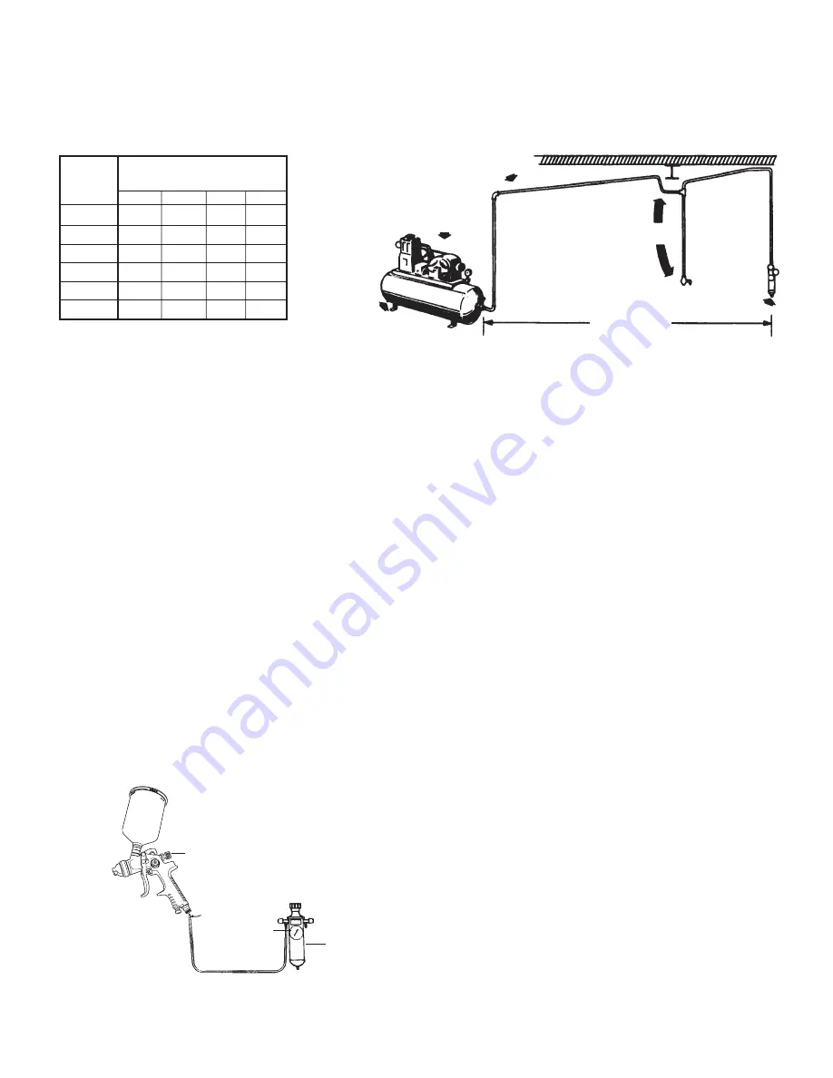
Never mount oil and water extractor on or near the air compressor.

During compression, air temperature is greatly increased. As the air cools down to room temperature, moisture 
condenses in the air line, on its way to the spray gun. Therefore, always mount the oil and water extractor at a point in
the air supply system where the compressed air temperature is lowest. 

Drain air lines properly.

Pitch all air lines back towards the compressor so that condensed moisture will flow back into the air receiver where 
it can be drained off. Each low point in an air line acts as a water trap. Such points should be fitted with an easily 
accessible drain. See diagram above.

Drain

Length of Pipe (ft.)

Air Flow

CFM

50

100

150

200

10

20

30

40

50

70

1/2"

3/4"

3/4"

1"

1"

1"

3/4"

3/4"

3/4"

1"

1"

1"

3/4"

1"

1"

1"

1-1/4"

3/4"

3/4"

1"

1"

1"

1-1/4"

AIR SUPPLY

Fluid
Control
Screw

Gravity
Feed
Cup

Atomization
Pressure Gauge

Oil & Water

Extractor

Drain

Oil and Water Extractor should be at least 25 ft. from the compressor, farther if possible.

25 Feet or

More

Install drain at

each low point

Compressor Unit

Pitch pipe back toward air receiver

Summary of Contents for 9004

Page 1: ... 9004 GRAVITY FEED SPRAY GUN CUP Operating Instructions Warning Information Parts Breakdown SPECIFICATIONS Fluid Orifice 1 4mm Air Inlet 1 4 NPT Rec Max Inlet Pressure 50 PSI CFM 3 1 at 50 PSI Nozzle Pressure 10 PSI ...

Page 2: ...h sound levels can cause permanent hearing loss Protect yourself from noise Noise levels vary with work surface Wear ear protectors When possible secure work with clamps or vise so both hands are free to operate tool Repetitive work motions awkward positions and exposure to vibration can be harmful to hands and arms Avoid inhaling dust or handling debris from work processes which can be harmful to...

Page 3: ...pray gun Therefore always mount the oil and water extractor at a point in the air supply system where the compressed air temperature is lowest Drain air lines properly Pitch all air lines back towards the compressor so that condensed moisture will flow back into the air receiver where it can be drained off Each low point in an air line acts as a water trap Such points should be fitted with an easi...

Page 4: ...zontal as shown here This provides a vertical fan shaped pattern which gives maximum even material coverage as the gun is moved back and forth parallel to the surface being finished Spray pattern may be infinitely adjusted from round to flat Set atomization pressure at no more than 50 PSI For optimum performance some materials may spray better at PSI ratings below 50 If unsure always test at PSI r...

Page 5: ...e of the gun 5 Oil gun daily Use a drop of lightweight machine oil on A fluid needle packing B air valve packing C trigger pivot point See Fig 1 for Location of Above Points 6 Caution Do not use lubricants which contain silicone Silicone may cause defects in the finish application AIR NOZZLE FLUID NOZZLE AIR VALVE ASSEMBLY 1 All nozzles and needles are made to exact standards They should be handle...

Page 6: ...nd body C Loose or defective swivel nut on siphon cup Fluid leakage from packing nut A Packing nut loose B Packing worn or dry A Tighten but not so tight as to grip needle B Replace packing or lubricate Dripping from fluid tip A Dry packing B Sluggish needle C Tight packing nut D Worn fluid nozzle or needle A Lubricate B Lubricate C Adjust D For pressure feed replace with new fluid nozzle and need...

Page 7: ...A 1722 1725A 1704 1713 1705 1706 1707 1708 1709 1710 1716 1726 1733 1715 1720 1714 1711 600CC 1729AL 1 9612N 0 1717 1718 1719 Optional Nozzle Kits Available 9004 1 4 1 4mm 9004 1 7 1 7mm 9004 2 0 2 0mm Nozzle Kits consist of 1 Air Cap 1 Fluid Needle 1 Fluid Nozzle 1700RK Includes all parts as asterisked on parts diagram ...

Page 8: ...Assembly 1714 Fan Adjustment 1715 Control Knob 1716 Paint Needle 1 4mm Standard 1717 Spring 1718 Lock for Fluid Control Knob 1719 Fluid Control Knob 1720 Screw 1722 Trigger 1724A Screw Nut 1725A Pin Clip 1726 Air Connection 1730A Spanner 1731 Socket Spanner 1732 Brush 1733 Air Adjusting Valve Assembly 9003PKG Material Filter 10 Pack 9612N 0 Hanger 600CC Replacement Aluminum Cup and Lid 1729AL 1 Ga...

Reviews:

Related manuals for 9004