background image

CASE 3

6 of 17

MOUNTING CONFIGURATIONS

                                                                                                                   Mounting Color Code:             Clamp Mount Range

D - 305 mm
E - 610 mm 

 Clamp mount allowable range:

Maximum  
Rear Load:

2400 Pa or 50 psi

Maximum  
Front Load:

5400 Pa or 113 psi

CASE 4:

 A structural rail

running perpendicular to
the length of the module
should be fixed between
each long side frame.
Clamps can be mounted
at the Fixed Clamp Mount
location as shown in the
color code key.

Installation Manual: SunEdison Silvantis P300 | M330/F330/D330

CENTER MOUNT CLAMPING 
(AP90/ATI TRACKERS ONLY)

5 of 16

Installation Manual: SunEdison Silvantis P300 | M330/F330/D330

Center Mount Clamping (AP90/ATI Trackers Only)

Maximum 
Rear Load: 

2400 Pa or 50 psi

Maximum 
Front Load:

5400 Pa or 113 psi

CASE 

4

Module Color Code:

Module Color Code:          Clamp Mount Range

CLAMP MOUNT 

LOCATIONS

MOUNTING CONFIGURATIONS

LOAD PARAMETERS

Clamp


Locations 

Version 17 

D

 – 3

05

 mm

E

 –

610

 mm

Clamp mount allowable range:

D

E

CASE 

4

:


A s

tructural rail 

running perpendicular to 
the length of the module 
should be fixed between 
each long side frame

.


Clamps can be mounted 
at the Fixed Clamp Mount 
location as shown in the 
color code key.

BACK VIEW

© Copyright 2014 SunEdison, Inc.

Summary of Contents for Silvantis D330

Page 1: ...Installation Manual for SunEdison SilvantisTM 72 cell Photovoltaic Modules Silvantis P300 Silvantis M330 F330 D330 ...

Page 2: ...INTEGRATED GROUNDING METHODS 11 5 3 OPTION C BOLT WIRE ASSEMBLY 11 5 3 OPTION D ALTERNATIVE GROUNDING 12 5 4 ELECTRICAL INSTALLATION WARNINGS 12 6 0 DISCLAIMER OF LIABILITY 12 7 0 MECHANICAL AND ELECTRICAL PARAMETERS AND SPECIFICATIONS 13 7 1 SILVANTIS P300 DETAILS 13 7 2 SILVANTIS M330 F330 D330 DETAILS 14 8 0 APPENDIX 15 8 1MODULEDETAILS 15 8 2 CENTER CLAMP MODULE INSTALLATION ILLUSTRATIONS 16 8...

Page 3: ...identification Damage to the glass surface or the anti reflective coating can impact the power output and overall efficiency of the system Scratches handling marks or any damage to the glass surface must be avoided For best performance and to avoid potential issues keep the front side of the module clean and free of obstructions including covers tape adhesives paint and debris 3 1 MAINTENANCE Chec...

Page 4: ... leave a module unsupported or unsecured Do not modify module frames in any way 3 3 SAFETY The following safety guidelines and best practices should be followed All installations must be performed in compliance with all applicable regional and local electrical codes or other national or international electrical standards Use insulated tools during installation troubleshooting and maintenance of ph...

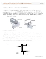
Page 5: ...our clamps over the front side Depending on the desired load capability of the array modules may be mounted either perpendicular or parallel to the structure rails Clamps can be mounted anywhere inside of the safe mounting range for each case illustrated below in table 4 2A If using bolts four mounting holes are provided on the rear side the module frame as shown in Appendix 8 1 Use a bolt stack n...

Page 6: ...d be fixed via bolts at the mounting holes between each long side frame or Clamps can be mounted at the Fixed Clamp Mount location as shown in the color code key CASE 2 Structural rails running parallel to the length of the module should be fixed via bolts at the mounting holes on each long side frame or Clamps can be mounted anywhere within the Clamp Mount Range as shown in the color code key CAS...

Page 7: ... MOUNT CLAMPING AP90 ATI TRACKERS ONLY 5 of 16 Installation Manual SunEdison Silvantis P300 M330 F330 D330 Center Mount Clamping AP90 ATI Trackers Only Maximum Rear Load 2400 Pa or 50 psi Maximum Front Load 5400 Pa or 113 psi CASE 4 Module Color Code Module Color Code Clamp Mount Range CLAMP MOUNT LOCATIONS MOUNTING CONFIGURATIONS LOAD PARAMETERS Clamp Locations Version 17 D 305 mm E 610 mm Clamp ...

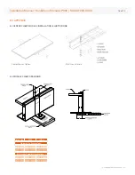
Page 8: ...Part Number 500000501 and 500000701 is permitted with SunEdison solar PV modules Structures manufactured by PanelClaw Inc use a special clamp or claw designed to attached to the flange of the PV module at all four corners on the two short frame ends PanelClaw is ULcertified for electric bonding and grounding See the PanelClaw installation guide for proper grounding management For proper placement ...

Page 9: ...ules in series Vmaxs equals the maximum system voltage Please refer to module data sheet for actual Vmax rating as some models are rated for 1000 V UL and 1000 V IEC Vocm equals the module open circuit voltage at coldest conditions for the site refer to local codes WARNING Installers shall adhere to all applicable local regional and national codes and regulations when designing and constructing th...

Page 10: ... conductive equipment and the earth in all scenarios Proper grounding is obtained by bonding all exposed metal equipment to each other by using a properly sized equiptment grounding conductor EGC SunEdison PV modules use a coated aluminum frame for corrosion resistance In order to ensure proper grounding the coating must be punctured by the grounding method A grounding wire composed of copper with...

Page 11: ...face of the frame Step 4 Place a bolt through the lug star washer and frame grounding hole Step 5 Secure the lug to the frame using a flat washer split washer and nut Step 6 Torque the bolt stack to approximately 1 5 2 3 N m or 1 1 1 7 ft lbs to ensure the star washer scratches the anodized frame 10 of 17 METRIC SET Stainless Steel Bolt M4 Stainless Steel Nut M4 Stainless Steel Flat Washer M4 Stai...

Page 12: ...ine compatibility 5 3 OPTION C BOLT WIRE ASSEMBLY 1 A grounding bolt assembly of at least minimum reccommended size see Option A must be attached at one of the designated aforementioned grounding hole locations Using only stainless steel hardware insert a stainless steel bolt first through the stainless steel cup washer and then through the grounding hole 2 Loosely add a stainless steel backing nu...

Page 13: ...specifications does not constitute a warranty expressed or implied SunEdison reserves the right to change the manual the module or specifications without prior notice The product warranty shall be VOID if handling and installation of the product does not conform to SunEdison s written installation instructions or if the product has been reworked repaired or otherwise modified in a manner not previ...

Page 14: ...800 W m2 600 W m2 400 W m2 200 W m2 IV CURVES AT MULTIPLE IRRADIANCES 25 C Current A Voltage V 10 5 0 0 1 2 3 4 5 6 7 8 9 15 20 25 30 35 40 45 50 Installation Manual SunEdison Silvantis P300 M330 F330 D330 Copyright 2014 SunEdison Inc 46 2 0 45 0 33 0 5 40 to 85 1000 UL IEC 9 10 15 0 5 Nominal Operating Cell Temperature NOCT C Temperature Coefficient of Pmax C Temperature Coefficient of Voc C Temp...

Page 15: ... 400 W m2 200 W m2 15 20 25 30 35 40 45 50 15 C 25 C 35 C 45 C Current A Voltage V 10 5 0 0 2 4 6 8 10 15 20 25 30 35 40 45 50 IV CURVES AT MULTIPLE IRRADIANCES 25 C IV CURVES AT MULTIPLE TEMPERATURES 1000 W m2 Copyright 2014 SunEdison Inc 47 0 2 0 45 0 33 0 05 40 to 85 1000 UL IEC 9 10 15 0 5 Nominal Operating Cell Temperature NOCT C Temperature Coefficient of Pmax C Temperature Coefficient of Vo...

Page 16: ...imension MM INCH Cable Length PHYSICAL PARAMETERS Module Weight kg G 22 0 Frame Material Anodized Aluminum Glass mm 3 2 Tempered ARC glass Connector S418 BizLink Amphenol PV Connector Cable length Tolerance 2 5 mm 52 5 mm 1 300 51 2 option available upon request please contact your local sales representative for more information Dimension tolerance range for A 3 mm B 3 mm and C 0 3 mm H BCC 1 300 ...

Page 17: ...AMP MODULE INSTALLATION ILLUSTRATIONS 8 3 MODULE CLAMP DRAWINGS 16 of 17 A 6 35 0 3 B 38 1 5 Module Clip Dimensions Dimension MM INCH Minimum Support Dimensions C 50 2 0 D 15 0 6 Installation Manual SunEdison Silvantis P300 M330 F330 D330 Copyright 2014 SunEdison Inc ...

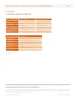
Page 18: ...SE DxxxByC 3z Amphenol Helios H4 PV Connector SE FxxxByC 3w S418 BizLink PV Connector SE FxxxByC 3z Amphenol Helios H4 PV Connector 17 of 17 2013 M330 F330 D330 P290 Install Guide_32 2014 SunEdison Inc All rights reserved SunEdison and the SunEdison logo are registered trademarks or trademarks of SunEdison Inc and or its affiliates in the United States and certain other countries All other tradema...

Reviews: