-17-
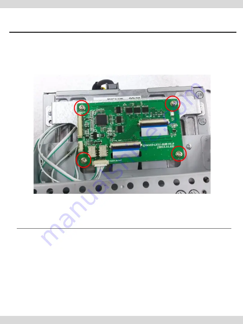
① TOUCH IN/OUT cables are linked to TOUCH IN/OUT of subboard, FFC
cable linked to LCD is connected to TTL_OUT
② Tighten the marked bolts to be fixed with bracket.
2. Installation
2.2 Installation
CarNavi-Tech
Page 1: ...el QVI LX11 1CH V7 1 SET Product Code LVTX 1CH 1203 005 SUNE TECHNOLOGY CO LTD No 9 Lane 606 Anping Rd Tainan City 70849 TAIWAN TEL 88662292246 FAX 88662288104 Http www sune tech com Shop http www carnavi tech com SKYPE sune_tech or hsin_han99 C a r N a v i T e c h ...
Page 2: ...or 2 Installation 2 1 Installation Diagram 2 2 Use caution 2 3 Installation 3 Settings 3 1 DIP Switch 3 2 Remote Control 3 3 OSD On Screen Display 3 4 Factory Mode 3 5 Rear Parking Guidelines 3 6 Touch Calibration 3 7 Remote button Input 4 Trouble Shooting 1 2 3 4 5 6 7 8 19 20 21 23 24 25 26 28 C a r N a v i T e c h ...
Page 3: ...lete test all vehicle electrical systems to ensure they operate correctly including lights horn brake lights and emergency flashers According to our sales policy any problems caused by user s mistake careless can not be guaranteed Caution All steps of installation should be done by well trained specialist During installation ignition key should be taken off and after all installation finish connec...
Page 4: ...DIA INTERFACE output specification 1 LCD output LCD performance 1 Audio output 2 CVBS output 4 Power specification Input power 8VDC 16VDC Consumed power 4WATT Max 5 Switch input mode External display skip function Through DIP switch user can control each video input Through remote control user can change input mode By pressing the MODE SWITCH the mode will be switched 1 1 Main Specifications C a r...
Page 5: ...just DVD NAVI on the screen Improvement in Screen Display User friendly interface Add Safe function While driving the screen shows the main page A MODE SWITCH button is provided to switch the mode 1 2 Features C a r N a v i T e c h ...
Page 6: ...RGB CVBS Rear camera Car Screen Input CAR MAIN BOARD A V 2 A V 3 VIDEO CIRCUIT VIDEO MUX MCU Power Input 8VDC 16VDC POWER CIRCUIT Dip S W A V OUT HEADREST MONITOR Remote control Switch for source toggle OEM Navi Button Can Signal Car Installation OEM LCD C a r N a v i T e c h ...
Page 7: ...OUCH OUT cable 1ea HTOUCH0004 REAR CAMERA POWER cable 1ea HARETC0002 IR cable 1ea MODE cable 1ea RGB cable 1ea HARETC0001 HNAVIC0004 HIRCAB0002 LVDS cable 1ea HLVDSC0020 Sub board 1ea Sub board Bracket 1ea PRESET0155 8P TOUCH cable 1ea HTOUCH0017 FFC cable 2ea FFCABL0036 8P FFC cable 1ea FFCABL0035 C a r N a v i T e c h ...
Page 8: ...ions 5 1 5 Exterior Dimension Width 125mm Length 105mm Height 21mm SUB BOARD LVDS IN BUTTON TOUCH IN OUT TTL_OUT TTL_IN LED POWER RGB IN 2 R CAM AV IN OUT DIP Switch TOUCH OUT TO NAVI LVDS OUT C a r N a v i T e c h ...
Page 9: ...GND ACC RGB REAR 9V OUT GND AV1 AV2 AV3 REAR C Audio L Audio R AV OUT Video Navigation Touch cable COMMAND LCD TOUCH IN OUT cable QDIS FFC cable QDIS FFC cable LVDS cable OEM TOUCH cable QDIS TOUCH cable In case of connecting the cable to Monitor s module directly Please use caution especially ESD It may cause the critical damage on the monitor C a r N a v i T e c h ...
Page 10: ...2 Installation 8 2 2 Installation Remove the monitor from the vehicle Detach Monitor s cover from the head unit C a r N a v i T e c h ...
Page 11: ... 9 Separate LCD part from the head unit Disconnect the OEM cables and remove the black plastic connector 2 Installation 2 2 Installation C a r N a v i T e c h ...
Page 12: ...ck connectors to FFC cables provided by us as shown on the left Link the new FFC cable to the place where OEM FFC cables were connected Refer to the right picture 2 Installation 2 2 Installation C a r N a v i T e c h ...
Page 13: ... 11 Assemble the bracket provided by us on the top of the body Holes where are marked in red are the place to be assembled with our bracket 2 Installation 2 2 Installation C a r N a v i T e c h ...
Page 14: ... 12 take out the FFC cable from the gap of the head unit and then link it to TTL IN of our Sub board 2 Installation 2 2 Installation C a r N a v i T e c h ...
Page 15: ... 13 Remove the cover of LCD part which was separated from the head unit 2 Installation 2 2 Installation C a r N a v i T e c h ...
Page 16: ... 14 Connect our touch FFC cable to the place where OEM touch cable was removed 2 Installation 2 2 Installation C a r N a v i T e c h ...
Page 17: ... 15 Connect touch out cable to our FFC cable and link touch in cable to OEM FFC cable 2 Installation 2 2 Installation C a r N a v i T e c h ...
Page 18: ... 16 Draw out our touch in out cables and FFC cables between gaps marked 2 Installation 2 2 Installation C a r N a v i T e c h ...
Page 19: ...UCH IN OUT cables are linked to TOUCH IN OUT of subboard FFC cable linked to LCD is connected to TTL_OUT Tighten the marked bolts to be fixed with bracket 2 Installation 2 2 Installation C a r N a v i T e c h ...
Page 20: ...tion OFF External Navigation Default ON DOWN OFF UP For example Use of DIP S W Input mode A V3 Navigation RGB OEM Navigation Not available Rear Camera When it is installed to CVBS4 DIP S W 1 OFF DIP S W 2 3 ON Input mode Skip DIP S W 4 OFF A V3 possible DIP S W 5 OFF DIP S W 6 ON DIP S W 7 ON CVBS4 possible DIP S W 8 OFF After resetting the DIP switch disconnect the power and reconnect the power O...
Page 21: ...image display Moving upward Moving downward Moving leftward If you press this button 2 seconds long you can access the factory mode Moving rightward If you press this button 2 seconds long you can reset all the data about user environment 3 Settings 3 2 Remote Control C a r N a v i T e c h ...
Page 22: ...OSD transparency H_POSITION OSD Move OSD horizontally V_POSITION OSD Move OSD vertically IMAGE BRIGHTNESS CONTRAST SHARPNESS USER IMAGE User settings among four options COLOR RED GREEN BLUE USER COLOR User settings UTIL FACTORY RESET Start Factory reset only for OSD function unable reset video position C a r N a v i T e c h ...
Page 23: ... USER IMAGE User settings among 4options OSD LANGUAGE Set OSD language only support English and Chinese TRANS Adjust OSD transparency H POSITION Move OSD horizontally V POSITION Move OSD vertically UTIL FACTORY RESET Factory reset only for OSD function unable reset video position C a r N a v i T e c h ...
Page 24: ...11 only IR MEMORY Enter input of remote button AVOUT SELECT DEFAULT AV1 AV2 AV3 DVD TYPE DTV TYPE PARK PARK ENABLE PARK SETUP REAR SELECT SAFE ENABLE IMAGE Change image location H POSITION Move image horizontally V POSITION Move image vertically FACTORY mode Press left button for 5 seconds UTIL2 CALIBRATION TOUCH ENABLE OEM SKIP HDMI SKIP FACTORY RESET C a r N a v i T e c h ...
Page 25: ...he power cable to the CAN cable of the car SAFE ENABLE Connect Safe cable of power cable to brake cable of hand brake ENABLE Shows only main page when Drive mode is engaged DISABLE Display the image you choose PARK ENABLE A PARK ENABLE ON Display the parking guide line as above B At this time when press OK button on the remote H POS will appear on the screen and able to move it horizontally PARK E...
Page 26: ...NO 2 The message will appear for 2 seconds as indicated above Then Calibration will be activated Press mark When it is done successfully it will show success Otherwise it will show failure FACTORY mode Press left button for 5 seconds C a r N a v i T e c h ...
Page 27: ...ut select menu you want to save To register DVD remote control button value select IR MEMORY DTV and follow below instructions For example a After select OK button on OSD menu press intended I Drive button b Indicated part above will flicker and press POWER on DVD remote control continue to next page FACTORY mode Press left button for 5 seconds What is IR MEMORY Mode Is to allow touch screen to co...
Page 28: ...SD menu Then you press OK button The message will appear to choose Yes or No Yes means it saves all settings and No means that it will not save the changed settings If data is saved DVD TYPE and DTV TYPE will be changed to USER automatically If you see SUCCESS on screen the data is saved clearly and you can control DVD via touch screen BUT you MUST change the option in FACTORY UTIL DVD to USER Ref...
Page 29: ...on has been done well Q Displayed image color is not proper too dark or unsuitable color A Go to Factory Mode Unit Factory reset if it does not work inform to manufacturer Q I cannot watch the rear camera on the screen A Set the DIP switch 7 as state ON Q Set mode not appear A Check DIP Switch Q OEM image is not displayed A Check interface s LCD In Out cable connection If the status keeps on infor...