background image

2

    Netra 440 Server Service Manual


• August 

2004

Locating Front Panel Components and 
LEDs

Front Panel Components

FIGURE


1-1

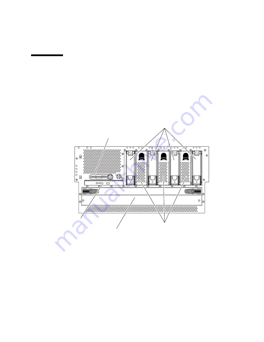
 shows the system components that you can access from the front panel. In 

the figure, the system door is opened. 

FIGURE


1-1 

Front Panel Components

For more detailed information about each of the front panel components, refer to the 

Netra 440 Server Product Overview

.

SCC

Fan trays 0-2

Hard drives

Power distribution board

DVD drive

System configuration 
card reader

Summary of Contents for Netra 440

Page 1: ...Sun Microsystems Inc www sun com Submit comments about this document at http www sun com hwdocs feedback Netra 440 Server Service Manual Part No 817 3883 11 August 2004 Revision A...

Page 2: ...opyright 2004 Sun Microsystems Inc 4150 Network Circle Santa Clara Californie 95054 Etats Unis Tous droits r serv s Sun Microsystems Inc a les droits de propri t intellectuels relatants la technologie...

Page 3: ...nel Components 2 Front Panel LEDs 3 Locating Back Panel Components and LEDs 12 Back Panel Components 12 Back Panel LEDs 14 Back Panel Slots and Ports 16 Locating Internal Components 19 2 Preparing to...

Page 4: ...talling a Fan Tray 0 2 39 Power Supplies 39 Removing a Power Supply 40 Installing a Power Supply 43 Hard Drives 44 Removing a Hard Drive 45 Installing a Hard Drive 49 Air Filter 50 Installing the Air...

Page 5: ...dules 81 Memory Interleaving 82 Removing a Memory Module 83 Installing a Memory Module 85 PCI Cards 86 Removing a PCI Card 86 Installing a PCI Card 92 ALOM System Controller Card 94 Removing the ALOM...

Page 6: ...25 Ethernet Ports 126 Network Management Port 127 Serial Management Port SERIAL MGT 128 SCSI Port 129 Alarm Port 131 C System Specifications 133 Physical Specifications 133 Electrical Specifications 1...

Page 7: ...Supply LEDs 15 TABLE 1 10 Back Panel External Ports 17 TABLE 1 11 ALOM External Ports 18 TABLE 1 12 Internal Components 20 TABLE 3 1 Calculating Air Filter Replacement Schedules for the Netra 440 Serv...

Page 8: ...33 TABLE C 2 AC Operating Power Limits and Ranges for Each Power Supply in the Netra 440 Server 134 TABLE C 3 AC Operating Power Limits and Ranges for the Netra 440 Server 134 TABLE C 4 DC Operating P...

Page 9: ...I Slots 16 FIGURE 1 10 Back Panel External Ports 17 FIGURE 1 11 ALOM System Controller Card Ports 18 FIGURE 1 12 Locating Internal Components 19 FIGURE 2 1 Opening the System Door 23 FIGURE 2 2 Locati...

Page 10: ...Fan Tray 3 Assembly 64 FIGURE 4 11 Loosening the Fan Tray 3 Assembly Captive Screw 65 FIGURE 4 12 Splitting the Fan Tray 3 Assembly Into Two Pieces 66 FIGURE 4 13 Removing the Air Diverter 69 FIGURE...

Page 11: ...ly 111 FIGURE 4 38 Disengaging the Power Distribution Board 112 FIGURE 4 39 Unscrewing the Motherboard Screws 113 FIGURE 4 40 Removing the Motherboard From the System 114 FIGURE A 1 Front Panel Compon...

Page 12: ...x Netra 440 Server Service Manual August 2004...

Page 13: ...server see the Netra 440 Server System Administration Guide 817 3884 xx For information about diagnosing problems with the server see the Netra 440 Server Diagnostics and Troubleshooting Guide 817 388...

Page 14: ...servicing cold swappable components This book also includes the following reference appendixes Appendix A contains an illustrated parts breakdown as well as a reference for field replaceable unit FRU...

Page 15: ...bCc123 The names of commands files and directories on screen computer output Edit your login file Use ls a to list all files You have mail AaBbCc123 What you type when contrasted with on screen comput...

Page 16: ...liable for any actual or alleged damage or loss caused by or in connection with the use of or reliance on any such content goods or services that are available on or through such sites or resources Ap...

Page 17: ...n com service contacting Sun Welcomes Your Comments Sun is interested in improving its documentation and welcomes your comments and suggestions You can submit your comments by going to http www sun co...

Page 18: ...xvi Netra 440 Server Service Manual August 2004...

Page 19: ...ts and LEDs on page 2 Locating Back Panel Components and LEDs on page 12 Locating Internal Components on page 19 For background information about the Netra 440 server and detailed instructions for ins...

Page 20: ...mponents that you can access from the front panel In the figure the system door is opened FIGURE 1 1 Front Panel Components For more detailed information about each of the front panel components refer...

Page 21: ...toggled on and off to verify that each one is working correctly LEDs located on the front panel work in conjunction with specific fault LEDs For example a fault in the power supply subsystem illumina...

Page 22: ...rvice Manual August 2004 FIGURE 1 2 shows the LEDs that are accessible from the front In the figure the system door is opened FIGURE 1 2 Front Panel LEDs SCC Hard drive LEDs Alarm LEDs Enclosure statu...

Page 23: ...ED provide a snapshot of the overall enclosure status The Locator LED helps you to quickly locate a specific system even though it may be one of numerous systems in a room The Locator LED is at the fa...

Page 24: ...are has detected a system fault This LED lights for any faults or failures detected in the following areas Motherboard CPU memory module DIMM Hard drive Fan trays Power supply In addition to the syste...

Page 25: ...to Remove This blue LED lights when the hard drive has been taken offline and is safe to remove from the system Service Required Reserved for future use Activity This green LED lights when the system...

Page 26: ...tray 3 located inside the system FIGURE 1 5 Fan Tray Status LEDs The following table describes the fan tray LEDs TABLE 1 4 Fan Tray LEDs Name Description Service Required This amber LED lights when t...

Page 27: ...ted by ALOM Information about the alarm indicators and dry contact alarm states is provided in TABLE 1 5 For more information about alarm indicators refer to the Sun Advanced Lights Out Manager Softwa...

Page 28: ...not fully loaded Off On Closed Open Transient state Solaris OS successfully loaded On Off Open Closed Normal operating state Watchdog timeout Off On Closed Open Transient state reboot Solaris OS Solar...

Page 29: ...This does not include the system power shutdown Based on a determination of the fault conditions the user can turn the alarm on using the Solaris platform alarm API or ALOM CLI For more information ab...

Page 30: ...t the power supplies shown in FIGURE 1 7 are for the DC powered servers the power supplies for the AC powered servers would be in the same location as those shown in FIGURE 1 7 but would have differen...

Page 31: ...from the rear of the system or through the top of the system For more detailed information about each of the rear panel components refer to the Netra 440 Server Product Overview 817 3881 xx TABLE 1 6...

Page 32: ...ernet LEDs is located on each Ethernet port The Ethernet LEDs operate as described in the following table TABLE 1 7 Ethernet LEDs Name Description Link Activity This green LED lights when a link is es...

Page 33: ...e LEDs operate as described in TABLE 1 9 TABLE 1 8 Network Management Port LED Name Description Link This green LED lights when an Ethernet connection is present TABLE 1 9 Power Supply LEDs Name Icon...

Page 34: ...Lights Out Manager ALOM card ports PCI Slots The Netra 440 server has three 33 MHz PCI slots and three 66 MHz PCI slots These are labeled on the back panel The Advanced Lights Out Manager ALOM card i...

Page 35: ...ort The system has one alarm port on the back panel which uses a DB 15 connector Serial port The system has one serial port TTYB on the back panel which uses a DB 9 connector Universal Serial Bus USB...

Page 36: ...11 FIGURE 1 11 ALOM System Controller Card Ports TABLE 1 11 ALOM External Ports Icon Description Serial RJ 45 port This is the default serial management connection for the system Ethernet port This p...

Page 37: ...e system s internal components from the top view FIGURE 1 12 Locating Internal Components TABLE 1 12 lists the internal components and shows whether they are hot swappable or cold swappable and whethe...

Page 38: ...e detailed information about each of the rear panel components refer to the Netra 440 Server Product Overview TABLE 1 12 Internal Components Hot or Cold Swappable Removal Point Component Hot Cold Rear...

Page 39: ...o keep the following guidelines in mind when servicing the system Except for removing and installing hard drives the system must be serviced by qualified service providers Only power supplies fan tray...

Page 40: ...ic Discharge on page 32 Controlling Server Power Refer to the following sections to power the server on and off Powering On the System on page 22 Powering Off the System on page 26 Powering On the Sys...

Page 41: ...vice to the serial management port using one of the methods described in the Netra 440 Server Installation Guide Otherwise use one of the methods for connecting to the system console also described in...

Page 42: ...twork management ports The system can take anywhere from 30 seconds to 20 minutes before text messages appear on the system monitor if one is attached or the system prompt appears on an attached termi...

Page 43: ...nnection a local graphics monitor connection ALOM connection or a TIP connection to the Netra 440 server See the Netra 440 Server Installation Guide for more information about connecting the Netra 440...

Page 44: ...ware system shutdown Note Pressing and releasing the On Standby button initiates a graceful software system shutdown Pressing and holding in the On Standby button for four seconds or turning the rotar...

Page 45: ...ystem shutdown Ensure that you stop and exit applications and shut down the operating environment before powering off the system Powering Off the System From the ok Prompt 1 Notify users that the syst...

Page 46: ...nds you need to set up an alphanumeric terminal connection a local graphics monitor connection ALOM connection or a TIP connection to the Netra 440 server See the Netra 440 Server Installation Guide 8...

Page 47: ...e sc prompt 7 At the ok prompt type the following commands You must set the auto boot variable to false and issue the reset all command to ensure that the system correctly initializes upon reboot If y...

Page 48: ...t the system LEDs see Front Panel LEDs on page 3 If the system encounters a problem during startup and the rotary switch is in the Normal position try restarting the system in diagnostics mode to dete...

Page 49: ...e top cover from the chassis then lift the cover up and off the chassis FIGURE 2 3 Installing the Top Cover 1 Insert the back edge of the top cover under the lip on the back panel 2 Grasp the latches...

Page 50: ...rap Antistatic mat or the equivalent Caution Printed circuit boards and hard drives contain electronic components that are extremely sensitive to static electricity Ordinary amounts of static from you...

Page 51: ...n replacement part Sun electrostatic discharge ESD mat Sun part number 250 1088 available through your Sun sales representatives Disposable ESD mat shipped with replacement parts or options 6 Use an a...

Page 52: ...34 Netra 440 Server Service Manual August 2004...

Page 53: ...without affecting the rest of the system s capabilities However you might have to prepare the operating system prior to the hot swap operation by performing certain system administration tasks In a N...

Page 54: ...t fan tray available before removing a fan tray A system can only run for approximately 15 minutes with only two fan trays operating before overheating occurs Caution The power supplies contain fans t...

Page 55: ...ge 32 2 Open the system door 3 Identify the fan tray to be removed and note the bay in which it is installed FIGURE 3 1 shows the location of the three fan trays Refer to the Netra 440 Server Diagnost...

Page 56: ...he handle slide the fan tray out of the bay Note When you reinstall the fan tray or a replacement fan tray ensure that you install the fan tray into the same bay as the one from which it was just remo...

Page 57: ...r supplies are online working and properly secured When removing a power supply using the hot swap operation you need to issue a software command to prepare the system for the hot swap operation This...

Page 58: ...s and you do not have a replacement available leave the failed power supply installed to ensure proper system cooling Caution Power supply hot swap operations should only be conducted by qualified ser...

Page 59: ...ence 4 Type the following ALOM command Where power supply is the name of the power supply to be removed For example to remove power supply 1 type the following command The OK to Remove LED lights on t...

Page 60: ...rver FIGURE 3 4 Removing a Power Supply 7 Slide the power supply out of the server chassis by pulling on the lever FIGURE 3 4 Caution Never insert your hand into the power supply bay while the system...

Page 61: ...with the power distribution board inside Ensure that the lever does not return to a rightmost position until the power supply engages with the power distribution board If the lever does return early t...

Page 62: ...fline to remove the logical software links to the hard drive and to reconfigure the file systems so that they now ignore the removed drive You might also have to reconfigure your application software...

Page 63: ...that are SCSI compatible and run at 15 000 revolutions per minute rpm Drives must be either the single ended or low voltage differential LVD type The SCSI target address SCSI ID of each hard drive is...

Page 64: ...e drive to spin down completely Caution When hot swapping a hard drive first ensure that the drive s blue OK to Remove LED is lit Then after disconnecting the drive from the SCSI backplane allow 30 se...

Page 65: ...e the bay in which it is installed FIGURE 3 5 shows the location of the four hard drives Refer to the Netra 440 Server Diagnostics and Troubleshooting Guide 817 3886 xx for more information about isol...

Page 66: ...eel the hard drive connector disengage from the SCSI backplane connector FIGURE 3 6 12 Holding the hard drive by the handle slide the hard drive out of the hard drive bay Note When you reinstall the h...

Page 67: ...ing the system console by the default method of connecting to the serial management port SERIAL MGT of the Netra 440 server Caution Do not hot swap drives without the correct preparations The system s...

Page 68: ...without an air filter for an extended period of time The filters are not designed to be cleaned so you must completely discard dirty filters and replace them with new clean filters The time frame in...

Page 69: ...mately 96 cubic feet per minute The part number for the air filter pack is X8217A 1 Open the system door 2 Locate the air filter behind the front door panel FIGURE 3 7 FIGURE 3 7 Locating the Air Filt...

Page 70: ...ugust 2004 3 Remove the air filter assembly from the front door panel FIGURE 3 8 FIGURE 3 8 Removing the Air Filter Installing the Air Filter 1 Install the air filter assembly into the front door pane...

Page 71: ...ng components are cold swappable DVD Drive on page 54 System Configuration Card SCC on page 57 System Configuration Card Reader on page 60 SCSI Backplane on page 68 Fan Tray 3 on page 74 CPU Memory Mo...

Page 72: ...s section The part numbers for the DVD drives are DVD RW drive F540 6068 X7424A DVD ROM drive F540 6067 X7423A Removing the DVD Drive 1 Power off the system See Powering Off the System on page 26 2 At...

Page 73: ...t of the system 6 If you are not replacing the DVD drive immediately install the DVD slot cover over the empty DVD space Insert the lower two tabs of the DVD cover into the two slots in the empty DVD...

Page 74: ...cover then lift it up and away from the empty DVD slot FIGURE 4 3 Store the DVD slot cover in a safe place FIGURE 4 3 Removing the DVD Slot Cover 2 Slide the DVD drive into the system until the two DV...

Page 75: ...you have replaced it with a new one with the same host ID and MAC address Caution Do not handle the system configuration card unless you need to transfer it to another system If you need to handle the...

Page 76: ...xx The part number for the system configuration card is F370 5155 Removing the System Configuration Card Caution Attempting to remove the system configuration card while the system is running causes a...

Page 77: ...and pull it out of the system Installing the System Configuration Card 1 Insert the system configuration card into the system configuration card reader which is at the left of the On Standby button F...

Page 78: ...avoid personal injury or damage to the system you must disconnect all AC or DC power cables before servicing the system configuration card reader 1 Power off the system See Powering Off the System on...

Page 79: ...the fan cable from the SCSI backplane FIGURE 4 6 FIGURE 4 6 Disconnecting the Fan Cable from the SCSI Backplane 8 Pull the rotary switch away from the system to remove it from the server FIGURE 4 7 FI...

Page 80: ...out of the connector FIGURE 4 8 Locating J18 and P1 Connectors 11 Remove the PCI cards from the system if necessary If short PCI cards are installed in the PCI slots at the rear of the system you do...

Page 81: ...ing and Replacing Cold Swappable Components 63 12 Unscrew the one screw that secures the fan tray 3 assembly to the system FIGURE 4 9 FIGURE 4 9 Unscrewing the Captive Screw for the Fan Tray 3 Assembl...

Page 82: ...0 Server Service Manual August 2004 13 Slide the fan tray 3 assembly to the rear of the system to disengage it and lift it up to remove it from the system FIGURE 4 10 FIGURE 4 10 Removing the Fan Tray...

Page 83: ...emoving and Replacing Cold Swappable Components 65 14 Unscrew the one screw to split the fan tray 3 assembly into two pieces FIGURE 4 11 FIGURE 4 11 Loosening the Fan Tray 3 Assembly Captive Screw Cap...

Page 84: ...the fan tray 3 assembly so the entire lower piece of the fan tray 3 assembly will be replaced FIGURE 4 12 Do not discard the upper piece of the fan tray 3 assembly you will attach that to the replacem...

Page 85: ...the two pieces completely together 3 Secure them together using the single captive screw FIGURE 4 11 4 Insert the fan tray 3 assembly into the system FIGURE 4 10 5 Secure the fan tray 3 assembly to th...

Page 86: ...t strap See Avoiding Electrostatic Discharge on page 32 3 Disconnect the AC or DC power cables from the back of the system 4 Disengage the hard drives and fan trays 0 1 and 2 from the SCSI backplane a...

Page 87: ...he fan tray 3 assembly FIGURE 4 13 7 Locate the air diverter and SCSI backplane FIGURE 4 13 FIGURE 4 13 Removing the Air Diverter 8 Unscrew the two screws from the top of the air diverter and remove t...

Page 88: ...SCSI system LED connector Fan tray 3 connector SCSI data to motherboard connector System configuration card reader to smart card connector FIGURE 4 14 shows the locations of these connectors FIGURE 4...

Page 89: ...owing connectors on the rear of the SCSI backplane the side facing the rear of the system Alarm input connector SCSI power to motherboard connector FIGURE 4 15 shows the locations of these connectors...

Page 90: ...al August 2004 11 Unscrew the two captive screws that secure the SCSI backplane to the system FIGURE 4 16 FIGURE 4 16 Removing the SCSI Backplane 12 Pull the SCSI backplane up and out of the system SC...

Page 91: ...SCSI data to motherboard connector System configuration card reader to smart card connector FIGURE 4 14 shows the locations of these connectors 4 Connect the cables to the following connectors on the...

Page 92: ...Overview 817 3881 xx Caution Fan tray 3 contains sharp moving parts Use extreme caution when servicing this fan tray The part number for fan tray 3 is F540 6069 Removing Fan Tray 3 Caution Do not att...

Page 93: ...Swappable Components 75 3 Remove the top cover See Removing the Top Cover on page 30 4 Disconnect the fan cable from the SCSI backplane FIGURE 4 17 FIGURE 4 17 Disconnecting the Fan Cable from the SC...

Page 94: ...ng so could overheat and seriously damage the system Caution The system supplies power to fan tray 3 even when the system is powered off To avoid personal injury or damage to the system you must disco...

Page 95: ...512 MB DIMMs X7426A 1 28 GHz CPU memory module with 4 GB memory 4 x 1 GB DIMMs X7416A Removing a CPU Memory Module If a CPU memory module fails POST diagnostics alerts ALOM to light the enclosure stat...

Page 96: ...t 2004 4 Identify the CPU memory module to be removed FIGURE 4 19 Refer to the Netra 440 Server Diagnostics and Troubleshooting Guide 817 3886 xx for information about isolating failed parts FIGURE 4...

Page 97: ...memory module ejector levers upward so that the CPU memory module connectors disengage from the CPU cage FIGURE 4 20 7 Pull the CPU memory module from the chassis by the levers and place it on an ant...

Page 98: ...es in the CPU cage Slide the CPU memory module into the chassis until the connectors on the module begin to engage the socket on the motherboard 5 Push down on both ejector levers simultaneously until...

Page 99: ...he DIMM slots and DIMM groups on a Netra 440 server CPU memory module Adjacent slots belong to the same DIMM group The two groups are designated 0 and 1 FIGURE 4 21 Memory Module Groups 0 and 1 You mu...

Page 100: ...erformance However actual performance results can vary depending on the system application Two way interleaving occurs automatically in any DIMM bank where the DIMM capacities in DIMM group 1 do not m...

Page 101: ...y metal part Always wear an antistatic grounding strap when you handle the DIMM For more information see Avoiding Electrostatic Discharge on page 32 Caution The CPU memory module and the DIMMs can be...

Page 102: ...ntil the memory module ejects from its socket FIGURE 4 22 Apply even pressure on both levers FIGURE 4 22 Removing a Memory Module 7 Grasp the top corners of the memory module and pull it up and out of...

Page 103: ...refully to avoid injury 1 Locate the slot into which you are installing the memory module 2 Rotate out the memory module ejector levers for that slot 3 Holding the bottom edge of the module parallel t...

Page 104: ...verall system availability by installing redundant network or storage interfaces on separate PCI buses For additional information refer to the Netra 440 Server System Administration Guide 817 3884 xx...

Page 105: ...isconnect any external cables attached to the faceplate of the PCI card 5 Disconnect any internal cables connected to the PCI card internal connectors 6 Remove the Phillips No 1 screw securing the car...

Page 106: ...88 Netra 440 Server Service Manual August 2004 FIGURE 4 24 Removing the Screw for a Long PCI Card...

Page 107: ...Cold Swappable Components 89 7 If you are removing a long PCI card raise the slotted PCI card retainer flap on the fan tray 3 assembly FIGURE 4 25 FIGURE 4 25 Lifting the Slotted PCI Card Retainer Fla...

Page 108: ...em and FIGURE 4 27 shows a long PCI card being removed from the system Hold the card by the faceplate and its opposite edge Pull up while rocking the card from end to end until it is freed from its sl...

Page 109: ...l a PCI filler panel and reassemble the system The PCI filler panel prevents debris from entering the system and ensures proper cooling a Slide the filler panel into the appropriate slot b Replace the...

Page 110: ...age 30 3 Locate an unused PCI slot Note PCI slots 2 4 and 5 can handle 33 MHz or 66 MHz cards PCI slots 0 1 and 3 are reserved for 33 MHz cards Note Installing a 33 MHz PCI card into a 66 MHz slot slo...

Page 111: ...he PCI card faceplate to the system back panel with the Phillips No 1 screw 7 If you are installing a long PCI card lower the slotted PCI card retainer flap on the fan tray 3 assembly onto the long PC...

Page 112: ...t is not a PCI compatible card The ALOM system controller card is not a hot swappable component Before installing or removing the ALOM system controller card you must power off the system and disconne...

Page 113: ...ou must disconnect the AC or DC power cables before servicing the ALOM system controller card 1 Power off the system See Powering Off the System on page 26 2 Attach the antistatic wrist strap See Avoi...

Page 114: ...ove the Phillips No 1 screw securing the card to the system back panel FIGURE 4 28 Caution Ensure that the power cords are disconnected from the system before removing the ALOM system controller card...

Page 115: ...motherboard 8 Using equal force on both ends of the ALOM system controller card pull the card straight up from its slot FIGURE 4 29 Hold the card by the faceplate and its opposite edge Pull up while r...

Page 116: ...e Ensure that you install the ALOM system controller card into the ALOM slot Though the ALOM system controller card might physically fit into a PCI slot it does not function if installed there Caution...

Page 117: ...stem controller card faceplate to the back panel with the Phillips No 1 screw 4 Connect the cables to the faceplate of the ALOM system controller card 5 Replace the top cover See Installing the Top Co...

Page 118: ...ard even when the system is powered off To avoid personal injury or damage to the system you must disconnect all AC or DC power cables before servicing the alarm card 1 Power off the system See Poweri...

Page 119: ...Components 101 4 Remove the two screws that secure the alarm port connector to the rear of the system FIGURE 4 31 FIGURE 4 31 Removing the Alarm Port Connector from the Rear of the System 5 Remove the...

Page 120: ...alarm card mounted on the inside of the server FIGURE 4 32 FIGURE 4 32 Locating the Alarm Card 7 Disconnect the Alarm In cable from the SCSI backplane FIGURE 4 32 Posts Front of server Rear of server...

Page 121: ...to the system you must disconnect all AC or DC power cables before servicing the alarm card 1 Insert the alarm card and cables into the system FIGURE 4 32 2 Align the three holes in the alarm card wit...

Page 122: ...st disconnect all AC or DC power cables before servicing the power distribution board 1 Power off the system See Powering Off the System on page 26 2 Attach the antistatic wrist strap See Avoiding Ele...

Page 123: ...E 4 33 This disconnects the power supply from the power distribution board FIGURE 4 33 Removing a Power Supply Unit b Pull the power supply out of its bay just enough to disengage the power supply con...

Page 124: ...door 6 Using a Phillips screwdriver loosen the two captive screws that secure the base of the power distribution board to the server FIGURE 4 34 7 Pull on the ejector latches and pull the power distri...

Page 125: ...of the power distribution board to fully seat the module all the way into the system 3 Using a Phillips screwdriver tighten the two captive screws to secure the base of the power distribution board t...

Page 126: ...r off the system See Powering Off the System on page 26 2 Attach the antistatic wrist strap See Avoiding Electrostatic Discharge on page 32 3 Disconnect the AC or DC power cables from the back of the...

Page 127: ...ppable Components 109 9 Locate the air diverter FIGURE 4 35 FIGURE 4 35 Removing the Air Diverter 10 Unscrew the two screws from the top of the air diverter and remove the air diverter from the system...

Page 128: ...RE 4 36 Lift up the connector ejector levers as far as they go to release the DVD cable end from the connector then pull the DVD cable out of the connector 13 Disconnect the P3 SCSI data cable end at...

Page 129: ...37 This disconnects the power supply from the power distribution board inside the server FIGURE 4 37 Removing a Power Supply b Pull the power supply out of its bay just enough to disengage the power s...

Page 130: ...n the two captive screws that secure the base of the power distribution board to the server FIGURE 4 38 b Pull on the ejector latches to unseat the power distribution board from the motherboard FIGURE...

Page 131: ...the back of the system disconnect any external cables attached to the motherboard Note and label connector locations 17 Unscrew the three Phillips No 2 screws that secure the motherboard to back of t...

Page 132: ...therboard From the System Installing the Motherboard Caution The system supplies power to the motherboard even when the system is powered off To avoid personal injury or damage to the motherboard you...

Page 133: ...Use the ejector levers at the front of the power distribution board to fully secure it against the motherboard Caution There are several pinch points on the power supplies so use caution when removin...

Page 134: ...er Service Manual August 2004 17 Replace the top cover See Installing the Top Cover on page 31 18 Connect the AC or DC power cables to the back of the system 19 Power on the system See Powering On the...

Page 135: ...d in the following tables are correct as of the manual publication date but are subject to change without notice Consult your authorized Sun sales representative or service provider to confirm a part...

Page 136: ...118 Netra 440 Server Service Manual August 2004 Front Panel Components and Fan Tray 3 Assembly FIGURE A 1 Front Panel Components and Fan Tray 3 Assembly 5 3 4 6 7 8 2 1...

Page 137: ...mber 1 Fan trays 0 1 or 2 F540 5855 2 73 GB SCSI hard drive F540 5924 XRA SC1N2 73G15K 3 Power distribution board F540 5854 4 Air filter X8217A 5 DVD RW drive F540 6068 X7424A 5 DVD ROM drive F540 606...

Page 138: ...120 Netra 440 Server Service Manual August 2004 Motherboard and Other Miscellaneous Components FIGURE A 2 Motherboard and Other Miscellaneous Components SER IAL MGT NET MGT 1 2 3 5 6 7 8 9 4...

Page 139: ...6370 5 1 28 GHz CPU memory module with 2 GB memory 4 x 512 MB DIMMs X7426A 5 1 28 GHz CPU memory module with 4 GB memory 4 x 1 GB DIMMs X7416A 6 1 GB memory 2 x 512 MB DIMMs F370 4939 X7403A 6 2 GB me...

Page 140: ...40 Server Service Manual August 2004 Rackmount Kits TABLE A 3 System Cables Part Part Number 23 inch 2 post Hard Mount Kit X7903A 600mm x 600mm 2 post Hard Mount Kit X7905A 19 inch 4 post Slide Mount...

Page 141: ...system back panel ports and pin assignments Topics covered in this appendix include Serial Port TTYB on page 124 USB Ports on page 125 Ethernet Ports on page 126 Network Management Port on page 127 Se...

Page 142: ...t can be accessed from the back panel FIGURE B 1 Serial Port Pin Numbering TABLE B 1 Serial Port Connector Signals Pin Signal Description Pin Signal Description 1 Data Carrier Detect 6 Data Set Ready...

Page 143: ...acked layout The ports can be accessed from the back panel FIGURE B 2 USB Connector Pin Numbering TABLE B 2 USB Ports Pin Numbering Pin Signal Description Pin Signal Description A1 5 V fused B1 5 V fu...

Page 144: ...faces operate at 10 Mbps 100 Mbps and 1000 Mbps FIGURE B 3 Ethernet Connector Pin Numbering TABLE B 3 Ethernet Connector Pin Signals Pin Signal Description Pin Signal Description 1 Transmit Receive Da...

Page 145: ...from the back panel This port needs to be configured prior to use FIGURE B 4 Network Management Port Pin Numbering TABLE B 4 Network Management Port Pin Signals Pin Signal Description Pin Signal Desc...

Page 146: ...d can be accessed from the back panel This port is the default connection to the system This is also the TTYA port for the system FIGURE B 5 Serial Management Port Pin Numbering TABLE B 5 Serial Manag...

Page 147: ...t Pin Signals Pin Signal Description Pin Signal Description 1 Data12 35 Data12 2 Data13 36 Data13 3 Data14 37 Data14 4 Data15 38 Data15 5 Parity1 39 Parity1 6 Data0 40 Data0 7 Data1 41 Data1 8 Data2 4...

Page 148: ...1 ATN 55 ATN 22 Ground 56 Ground 23 BSY 57 BSY 24 ACK 58 ACK 25 RST 59 RST 26 MSG 60 MSG 27 SEL 61 SEL 28 CD 62 CD 29 REQ 63 REQ 30 I O 64 I O 31 Data8 65 Data8 32 Data9 66 Data9 33 Data10 67 Data10 3...

Page 149: ...BLE B 7 Alarm Port Signals Pin Signal Description Pin Signal Description 1 RESERVED 9 ALARM1_NC 2 RESERVED 10 ALARM1_COM 3 NC 11 ALARM2_NO 4 NC 12 ALARM2_NC 5 ALARM0_NC1 1 The ALOM software sets the A...

Page 150: ...132 Netra 440 Server Service Manual August 2004...

Page 151: ...ecifications on page 136 Clearance and Service Access Specifications on page 136 Physical Specifications TABLE C 1 Physical Specifications Netra 440 Server Measu3re U S Metric Width 17 32 inches 440 0...

Page 152: ...the fusing and cabling you need to deliver power to your equipment However these figures represent worst case scenarios TABLE C 2 AC Operating Power Limits and Ranges for Each Power Supply in the Netr...

Page 153: ...the Netra 440 server as a whole TABLE C 4 DC Operating Power Limits and Ranges for Each Power Supply in the Netra 440 Server Description Limit or Range Operating input voltage range 40 VDC to 75 VDC M...

Page 154: ...C 41 F to 40 C 104 F Short term1 5 C 23 F to 55 C 131 F 1 Short term no more than 96 hours temperature and humidity limits apply to servers with altitudes up to 1800 m 5905 44 ft 40 C 40 F to 70 C 158...

Page 155: ...tions This appendix illustrates the connector locations on the system boards It contains the following sections Motherboard Connectors on page 138 SCSI Backplane Connectors on page 139 ALOM System Con...

Page 156: ...memory module 66 MHz PCI slots connectors Power distribution board Power distribution board 2 4 and 5 Rear LED connector Serial TTYB USB connectors Ethernet connectors SCSI external connector 33 MHz...

Page 157: ...plane Connectors FIGURE D 2 SCSI Backplane Connectors Front Hard drive connectors Fan tray 0 1 and 2 connectors System configuration card reader to smart card connector SCSI data to Fan tray 3 connect...

Page 158: ...140 Netra 440 Server Service Manual August 2004 FIGURE D 3 SCSI Backplane Connectors Rear Alarm input connector SCSI power to motherboard connector...

Page 159: ...pendix D Board Connector Locations 141 ALOM System Controller Card Connectors FIGURE D 4 ALOM System Controller Card Connectors SERIAL MGT NETMGT Serial management connector Network management connect...

Page 160: ...142 Netra 440 Server Service Manual August 2004...

Page 161: ...g 103 location 102 part number 100 removing 100 alarm LEDs critical 10 description 9 location 4 9 major 10 minor 11 states 10 user 11 alarm port description 17 location 12 17 pinouts 131 ALOM system c...

Page 162: ...4 environmental specifications 136 Ethernet connection LEDs description 14 location 14 Ethernet ports description 17 location 12 17 pinouts 126 F fan cable connecting 67 77 disconnecting 61 75 locatio...

Page 163: ...rays 0 2 location 4 8 front panel 4 hard drive description 7 location 4 7 Locator system status LED 6 network management port NET MGT description 15 location 14 OK to Remove hard drive LED 7 Power OK...

Page 164: ...ard 104 power supplies 40 SCSI backplane 68 system configuration card 58 system configuration card SCC reader 60 PCI card installing 92 part number 86 removing 86 PCI card slots description 16 locatio...

Page 165: ...ation rules 94 location 18 pinouts 128 serial port TTYB description 17 location 12 17 pinouts 124 service access specifications 136 service guidelines 21 Service Required fan tray 0 2 LED 8 Service Re...

Page 166: ...148 Netra 440 Server Service Manual August 2004 U USB ports description 17 location 12 17 pinouts 125 user alarm LED 11...

Reviews: