background image

Chapter 2

Parts Replacement

37

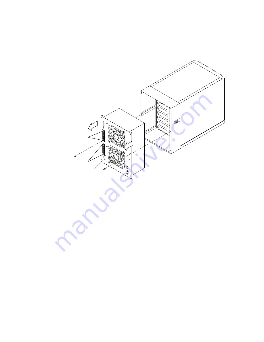
FIGURE 2-5

Removing the Power Supply

7. Carefully pull the power supply out from the unit using the pull strap and set it

aside (

FIGURE 2-6

).

The connector at the back of the power supply connects to the backplane
(

FIGURE 2-6

). Because of this connection, the power supply will not slide out of the

unit easily. Slowly work the power supply loose from the connector as you remove it
from the enclosure.

To Install the New Power Supply

1. Align the power supply at the back of the unit so that the connector plug on the

power supply lines up with the connector on the backplane

FIGURE 2-6

).

Pull strap

Jack screws

Jacks crews

Phillips screw

Summary of Contents for 711

Page 1: ...o Road Palo Alto CA 94303 4900 USA 1 650 960 1300 fax 1 650 969 9131 A Sun Microsystems Inc Business Sun StorEdge MultiPack User s Guide Part No 805 3954 10 Revision A February 1998 Sun Microsystems Computer Company ...

Page 2: ...98 Sun Microsystems Inc 901 San Antonio Road Palo Alto CA 94303 Etats Unis Tous droits réservés Ce produit ou document est protégé par un copyright et distribué avec des licences qui en restreignent l utilisation la copie la distribution et la décompilation Aucune partie de ce produit ou document ne peut être reproduite sous aucune forme par quelque moyen que ce soit sans l autorisation préalable ...

Page 3: ... may void the authority granted to the user by the FCC to operate this equipment FCC Class B Notice This device complies with Part 15 of the FCC Rules Operation is subject to the following two conditions 1 This device may not cause harmful interference 2 This device must accept any interference received including interference that may cause undesired operation Note This equipment has been tested a...

Page 4: ...gulations Cet appareil numérique de la classe A respecte toutes les exigences du Règlement sur le matériel brouilleur du Canada DOC Class B Notice Avis DOC Classe B This Class B digital apparatus meets all requirements of the Canadian Interference Causing Equipment Regulations Cet appareil numérique de la classe B respecte toutes les exigences du Règlement sur le matériel brouilleur du Canada ...

Page 5: ... Lines EN61000 3 2 IEC1000 3 2 1994 Pass Safety This equipment complies with the following requirements of Low Voltage Directive 73 23 EEC EC Type Examination Certificates EN60950 IEC950 1993 TUV Rheinland Certificate S9577298 EN60950 w Nordic Deviations CB Scheme Certificate UL672 138989 USA Supplementary Information This product was tested and complies with all the requirements for the CE Mark w...

Page 6: ...vi Book Title Month 1998 ...

Page 7: ...ipment Sun Microsystems is not responsible for regulatory compliance of a modified Sun product Placement of a Sun Product Caution Do not block or cover the openings of your Sun product Never place a Sun product near a radiator or heat register Failure to follow these guidelines can cause overheating and affect the reliability of your Sun product SELV Compliance Safety status of I O connections com...

Page 8: ...ie Ihr Gerät installieren Beachten Sie alle auf den Geräten angebrachten Warnhinweise und Anweisungen Vergewissern Sie sich daß Spannung und Frequenz Ihrer Stromquelle mit der Spannung und Frequenz übereinstimmen die auf dem Etikett mit den elektrischen Nennwerten des Geräts angegeben sind Stecken Sie auf keinen Fall irgendwelche Gegenstände in Öffnungen in den Geräten Leitfähige Gegenstände könnt...

Page 9: ...ändig zu unterbrechen müssen Sie das Netzkabel von der Steckdose abziehen Schließen Sie den Stecker des Netzkabels an eine in der Nähe befindliche frei zugängliche geerdete Netzsteckdose an Schließen Sie das Netzkabel nicht an wenn das Netzteil aus der Systemeinheit entfernt wurde Lithiumbatterie Achtung CPU Karten von Sun verfügen über eine Echtzeituhr mit integrierter Lithiumbatterie Teile Nr MK...

Page 10: ...onformité réglementaire d un produit Sun qui a été modifié Positionnement d un produit Sun Attention pour assurer le bon fonctionnement de votre produit Sun et pour l empêcher de surchauffer il convient de ne pas obstruer ni recouvrir les ouvertures prévues dans l appareil Un produit Sun ne doit jamais être placé à proximité d un radiateur ou d une source de chaleur Conformité SELV Sécurité les ra...

Page 11: ...ridad Para su protección observe las siguientes medidas de seguridad cuando manipule su equipo Siga todas los avisos e instrucciones marcados en el equipo Asegúrese de que el voltaje y la frecuencia de la red eléctrica concuerdan con las descritas en las etiquetas de especificaciones eléctricas del equipo No introduzca nunca objetos de ningún tipo a través de los orificios del equipo Pueden haber ...

Page 12: ...a de tierra La siguiente advertencia se aplica solamente a equipos con un interruptor de encendido que tenga una posición En espera Precaución El interruptor de encendido de este producto funciona exclusivamente como un dispositivo de puesta en espera El enchufe de la fuente de alimentación está diseñado para ser el elemento primario de desconexión del equipo El equipo debe instalarse cerca del en...

Page 13: ...ri returneres apparatleverandøren Sverige VARNING Explosionsfara vid felaktigt batteribyte Använd samma batterityp eller en ekvivalent typ som rekommenderas av apparattillverkaren Kassera använt batteri enligt fabrikantens instruktion Danmark ADVARSEL Litiumbatteri Eksplosionsfare ved fejlagtig håndtering Udskiftning må kun ske med batteri af samme fabrikat og type Levér det brugte batteri tilbage...

Page 14: ...xiv Sun StorEdge MultiPack User s Guide February 1998 ...

Page 15: ...ation on the Web xix Sun Welcomes Your Comments xix 1 Installation Considerations 21 Minimum Hardware 21 Placement 22 Daisy Chaining SCSI Devices 23 UltraSCSI 23 Fast Wide or Narrow SCSI Buses 23 Installing a Terminator 24 Sun StorEdge MultiPack Disks 25 Sun StorEdge MultiPack Addresses 25 26 2 Sun StorEdge MultiPack LEDs 27 Status LEDs 27 ...

Page 16: ...ront Disk Drive LEDs 27 3 Parts Replacement 31 Sun StorEdge MultiPack Disk Drives 31 Disk Drive Replacement 32 Power Supply Units 35 A Internal and External CableLengths 39 External SCSI Cable Length 39 Internal SCSI Cable Length 40 ...

Page 17: ...more specific information on commands and procedures The Solaris Handbook for SMCC Peripherals that corresponds to your operating system AnswerBook on line software which contains the complete set of documentation supporting the Solaris 1 x or Solaris 2 x environments Other software documentation that you received with your system The Solaris Handbook for SMCC Peripherals for your system software ...

Page 18: ...vice Sun StorEdge MultiPack Service Manual 805 3956 xx Hot plug Instructions Sun StorEdge MultiPack Storage Guide 805 3955 xx TABLE P 2 SunExpress Contact Information Country Telephone Fax Belgium 02 720 09 09 02 725 88 50 Canada 1 800 873 7869 1 800 944 0661 France 0800 90 61 57 0800 90 61 58 Germany 01 30 81 61 91 01 30 81 61 92 Holland 06 022 34 45 06 022 34 46 Japan 0120 33 9096 0120 33 9097 L...

Page 19: ...ocs sun com archive or search for a specific book title or subject at http docs sun com Sun Welcomes Your Comments We are interested in improving our documentation and welcome your comments and suggestions You can email your comments to us at smcc docs sun com Please include the part number of your document in the subject line of your email ...

Page 20: ...xx Sun StorEdge MultiPack User s Guide February 1998 ...

Page 21: ...s at the lower speed Only one Sun StorEdge MultiPack enclosure loaded with up to six disk drives can be connected on each bus for UltraSCSI operation The number of UltraSCSI host adapters you can install is limited only by the number of slots available on your computer Each wide or UltraSCSI host adapter you add increases the number of SCSI devices you can connect to your computer by 15 addresses ...

Page 22: ... See Appendix A for tables of SCSI bus lengths Place the Sun StorEdge MultiPack enclosure on its feet Because the drive replacement panel opens at the left side of the unit place the Sun StorEdge MultiPack box front facing you at the left side of your computer or where the panel can open freely Leave three or more inches of space in front of the air vents on both the Sun StorEdge MultiPack enclosu...

Page 23: ...host port of a host interface or to a host adapter If you connect your Sun StorEdge MultiPack enclosure to the on board host port of your computer you can use only a 8 meter cable You can use a 2 meter cable if you connect it to a host adapter Do not use an external terminator Caution Chaining other external SCSI devices at any point in the chain with the Sun StorEdge MultiPack enclosure causes th...

Page 24: ...minator For UltraSCSI operation do not use the external terminator The on board autoterminator functions in UltraSCSI mode For Fast operation install the terminator on the SCSI OUT port of a Sun StorEdge MultiPack unit after you have connected it to the host Sun StorEdge MultiPack SPARCstorage MultiPack and SPARCstorage UniPack Configuration Guidelines External Subsystem Daisy Chain Configurations...

Page 25: ...SMCC Peripherals appropriate to your particular system software for information on setting up the disk drives Refer to the AnswerBook on line documentation that came with your operating system for more information Sun StorEdge MultiPack Addresses When you connect a Sun StorEdge MultiPack unit to your system you must choose either SCSI addresses 1 6 or SCSI addresses 9 14 for your drives FIGURE 1 2...

Page 26: ...ge MultiPack User s Guide February 1998 FIGURE 1 3 Sun StorEdge MultiPack Six Drive Back Panel With SCSI Switch 9 14 1 6 IN OUT Power switch Power connector 9 14 and 1 6 SCSI switch Auto termination indicators LEDs ...

Page 27: ...at power is on Front Disk Drive LEDs When lit the LEDs on the front of the enclosure indicate which drive bays have hard disk drives The LEDs blink when a particular drive is active on a SCSI bus Note With heavy activity an LED can be off for ten seconds While a drive is being formatted the LED can be off for ten or more minutes During the power on process the drives spin up sequentially An LED ma...

Page 28: ...et addresses both the front and internal LEDs 9 14 light If the enclosure has the minimum two drives LEDs 9 and 10 light and blink when the drive is active FIGURE 2 2 If you have opted to use the 1 6 SCSI target addresses and the enclosure has the minimum two drives LEDs 1 and 2 light The auto termination LED on the back of the unit goes out when an external terminator is installed 9 11 10 12 14 1...

Page 29: ...Chapter 2 Sun StorEdge MultiPack LEDs 29 FIGURE 2 2 Interior LEDs and SCSI Target Addresses 9 12 1 4 10 13 2 5 11 14 3 6 HI LO LO LO HI HI ...

Page 30: ...30 Sun StorEdge MultiPack User s Guide February 1998 ...

Page 31: ...ives The Sun StorEdge MultiPack disks must have brackets similar to the ones already in the unit FIGURE 2 1 shows one type of bracket used on Sun StorEdge MultiPack drives Instructions for a different type of bracket may differ FIGURE 2 1 Disk Drive With Bracket ...

Page 32: ...op that activity before removing the drive You can do this without bringing down the operating system or powering down the Sun StorEdge MultiPack unit For more details on hot plugging refer to the Sun StorEdge MultiPack Storage manual that came with your unit A number of symptoms can indicate that a disk drive needs replacement To determine which drive is bad refer to the system administration doc...

Page 33: ...un StorEdge MultiPack unit remains connected to the wall plug to ensure a ground 4 Unlatch the drive bracket handle on the right to release it FIGURE 2 1 5 Pull the bracket handle out and swing it open until it pushes against the chassis 6 Continue pushing the handle against the chassis applying mild pressure until the drive pops out from the connector 7 Slide the drive out and set it on an antist...

Page 34: ...u replace a defective drive replace it into the same bay the old one occupied 1 With the bracket extended insert the disk drive into the drive bay aligning the connector on the drive with the connector on the backplane FIGURE 2 3 2 Slowly and gently push the drive in until the metal drive handle contacts the enclosure metal rib Note Make sure you insert the drive in the correct drive bay to mate w...

Page 35: ...ting system and turn the power off before you open the Sun StorEdge MultiPack unit to remove the power supply To Remove the Old Power Supply 1 Refer to the Solaris Handbook for SMCC Peripherals that came with your computer to shut down the operating system The handbook is included in the AnswerBook online documentation 2 Shut off the power to the Sun StorEdge MultiPack unit FIGURE 1 1 3 Disconnect...

Page 36: ...k Cover 4 Remove the three screws and the lock block that hold the back cover FIGURE 2 4 5 Remove the two Phillips screws that attach the power supply to the unit FIGURE 2 5 6 Remove the four 3 16 inch jackscrews that secure the board to the power supply FIGURE 2 5 Phillips screw ...

Page 37: ...he backplane FIGURE 2 6 Because of this connection the power supply will not slide out of the unit easily Slowly work the power supply loose from the connector as you remove it from the enclosure To Install the New Power Supply 1 Align the power supply at the back of the unit so that the connector plug on the power supply lines up with the connector on the backplane FIGURE 2 6 Pull strap Jack scre...

Page 38: ...FIGURE 2 5 4 Insert and tighten the two screws to secure the power supply in the enclosure FIGURE 2 5 5 Push the pull strap back into the power supply casing The pull strap should be pushed in enough so that it is not in the way when you replace the back cover 6 Replace the back cover FIGURE 2 2 7 Insert and tighten the three corner screws and install the lock block to hold the back panel to the e...

Page 39: ...adapter you can use either a 8 meter cable or a 2 meter cable To directly connect a Sun StorEdge MultiPack enclosure to your desktop system or to daisy chain it to another SCSI peripheral use the UltraSCSI cable that ships with the unit Caution Using cables other than those recommended by Sun may result in data loss TABLE A 1 SCSI External Cable Lengths Cables Meters Inches 68 68 pin cable 0 8 31 ...

Page 40: ...3 11 8 Sun StorEdge MultiPack 0 9 35 4 Desktop Disk Pack tape disk CD ROM 0 3 11 8 Ultra 1 Model 140 Model 170 0 9 35 4 Ultra 1 Creator and Ultra 1 Creator 3D 0 9 35 4 Ultra Enterprise 450 0 9 35 4 Ultra 2 Creator and Ultra 2 Creator 3D 0 9 35 4 Ultra 30 0 9 35 4 SPARCstation 5 20 1 6 62 6 SPARCstation 4 1 2 48 0 SPARCstation 10 LX SPARCclassic 0 9 35 4 SPARCstation Voyager 0 4 15 7 SPARCserver 10...

Reviews: