background image

36

H

YDRAULIC

 F

ITTING

 I

NSTRUCTION

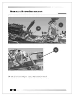
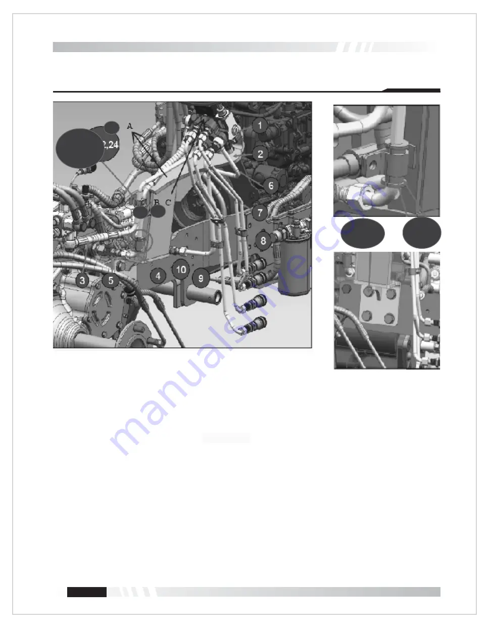
1. Kindly dismantle RH tire, no. 36 & cup holder on the fender for the following assembly.
2. Use necessary precautions and safety.
3. Preassemble the bracket A(no. 1), B(hose 4), C & valve(no. 1), (no. 14,15)
4. Do not torque “B(hose 4) connection on the valve complete full assembly and then tighten
    the banjo bolt.

33, 34

11, 12, 13

B

C

A

21,22,24

Summary of Contents for LX85

Page 1: ...OPERATOR MANUAL L 85 X TM www summittractors com LOADER S...

Page 2: ...OPERATOR S MANUAL Publication No Revision 00 Released DEC 21 Summit Tractors LLC 3379 Peachtree Road NE Suite 555 Atlanta GA 30326 Summit LX85 Front End Loader...

Page 3: ......

Page 4: ...CONTENTS 1 2 3 4 14 15 18 22 22 23 24 25 26 28 35 44 1 Troubleshooting for 3rd function valve...

Page 5: ...odel and serial number is stamped on a plate on the outside of the right hand loader arm Please quote both numbers when ordering spare parts or accessories IDENTIFICATION 2 Location of Loader Serial N...

Page 6: ...ers powered by the tractor s hydraulic system and controlled by the operator The front end loader is attached to or detached from the tractor quickly effortlessly by quick change system The support le...

Page 7: ...SAFETY INSTRUCTIONS 4 prevent...

Page 8: ...he loader with bare feet in any circumstance Danger a Warning Read and follow all instructions in the operators manual before attempting to operate the tractor and the loader failure to comply with th...

Page 9: ...fire accidents or personal injury Make sure that the attachment is properly installed adjusted and is in good operating condition in Do not modify the loader under any circumstance Modification can d...

Page 10: ...osition See illustration contents a Max 10 km h Max 6 mile h 6 mph the bucket Use left pedal as a brake a your surroundings If you have questions regarding the operating manual or require additional i...

Page 11: ...8 SAFETY INSTRUCTIONS front end loader While traveling on road please ensure that SMV slow moving vehicle emblem placed in...

Page 12: ...SAFETY INSTRUCTIONS All gears and PTO should be in neutral position the loader h front end loader is used eliminate falling system ing pipes or connections unattended Replace these parts with genuine...

Page 13: ...10 SAFETY INSTRUCTIONS Left side view Right side view 85 LX 85 LX...

Page 14: ...11 SAFETY INSTRUCTIONS towards operator side Top view...

Page 15: ...12 SAFETY INSTRUCTIONS...

Page 16: ...FETY INSTRUCTIONS This product can expose you to chemicals which is known to the state of California to cause cancer and reproductive harm For more information got to www P65Warnings ca gov d 9 stop 1...

Page 17: ...Summit Summit The control valve supplied with your loader with factory preset pressure All the warranties will be voided if the preset pressure is tampered Use cylinder lock at position A while maint...

Page 18: ...OPERATION 15 w w z z While operating on loose soil slippery surface or on descending slope follow the below steps in...

Page 19: ...250 300 Kgs n n P S front end loader should be leak free attached with hitch The control lever of the loader is located at the right side of operator s seat The preceding lever is used to control the...

Page 20: ...17 OPERATION Oil top up is not required for this tractor on a loader assembly 85 LX Part description Torque Grease nipple 12 Lbft 16 Nm Pin bolts 16 Lbft 22 Nm...

Page 21: ...WORK INSTRUCTIONS 18 Summit LX85 r...

Page 22: ...WORK INSTRUCTIONS 19 31 5 inches 800mm 0 39 inches 10mm 31 5 Inches 800mm Fig 1...

Page 23: ...WORK INSTRUCTIONS 20 Summit loader cross member is only one type hood as shown in above fig 1...

Page 24: ...WORK INSTRUCTIONS 21 clearance between Refer hydraulic fitting instruction section Check TANK SUPPLY Power Beyond PB...

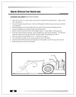
Page 25: ...22 QUICK DETACH INSTRUCTIONS 4 feet 1 2m 2 inches 50mm 20 30mm l d l e a...

Page 26: ...23 QUICK DETACH INSTRUCTIONS f t 48 inch Electric Front Remotes the f t Electric Front Remotes the RE INSTALLATION OF THE LOADER...

Page 27: ...QUICK DETACH INSTRUCTIONS 24 Step 3 In some models an adjustable clamp is provided The clamp can be unbolted and adjusted as per desired applications and understanding R pins...

Page 28: ...r activates the valve When the button is pushed and lever moved towards the right direction the attachment opens When lever is moved towards the right the attachment closes 7 b If your loader has a 4...

Page 29: ...t 10 hours then every 50 hours thereafter M12 10 9 grade at 89 3 lbft 121Nm Visually inspect attachment subframe and decal for integrity Visually inspect and torque all bolts fasteners and hydraulic f...

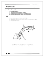
Page 30: ...27 MAINTENANCE Note The above drawing show the location of the greaseable pins a j c a s d 85 LX...

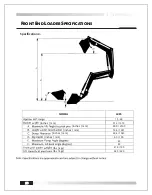
Page 31: ...R SPECIFICATIONS 85 0 2160 76 8 1951 6 0 150 419 190 43 45 60 6 1540 LX85 15 26 51 6 1310 inches mm inches mm inches mm inches mm inches mm lbs kgs lbs kgs 925 420 Specifications Note l l b h H u c d...

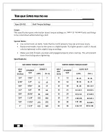
Page 32: ...29 TORQUE SPECIFICATIONS Lbft N m N m Lbft 33 35 24 25 65 71 110 122 180 195 270 299 380 413 530 585 890 1011 81 90 133 144 199 221 280 305 391 432 656 747 48 53 metric imperials...

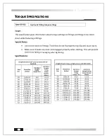
Page 33: ...30 TORQUE SPECIFICATIONS Lbft Lbft Hydraulic fitting torque settings b b leakaging when tightening...

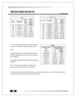
Page 34: ...31 TORQUE SPECIFICATIONS Lbft Lbft Lbft p seals and...

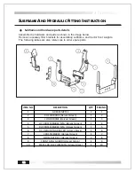
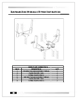
Page 35: ...er spare parts Subframe and hardware parts details ITEM NO DESCRIPTION QTY ITEM NO 1 GREASE NIPPLE 2 1 2 RH SUBFRAME Harvest Green 1 2 3 LH SUBFRAME Harvest Green 1 3 4 LH CROSS MEMBER MTG Harvest Gre...

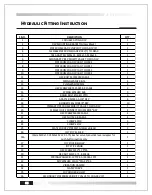
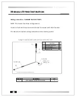
Page 36: ...LIC FITTING INSTRUCTION S NO DESCRIPTION QTY 3 HEX BOLT M16X2X180 SEMI THREAD 2 4 PLAIN WASHER M16 2 5 SPRING WAHSER M16 2 6 HEX BOLT M14X2X40 SEMI THREAD 2 7 PLAIN WASHER M14 2 8 SPRING WAHSER M14 2...

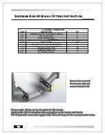
Page 37: ...3 HEX BOLT M16X2X50 SEMI THREAD 8 14 PLAIN WASHER M16 20 15 SPRING WAHSER M16 12 16 NYLOC NUT M16X2 4 X MEMBER CONNECTION MAIN PLATE Spacer to be removed form tractor with mid mower both LH RH Please...

Page 38: ...RING WASHER M8 3 16 BANJO BOLT 16 4 19TPI 3 17 ADAPTER M18X1 5 3 8 BSP 4 18 BONDED SEAL FOR3 8 BSP 10 19 PRIMARY PIPE FROM PRIORITY VALVE TO 2DA DCV 1 20 FEMALE QUICK CONNECT COUPLER3 8 BSP 4 21 HEX S...

Page 39: ...on the fender for the following assembly 2 Use necessary precautions and safety 3 Preassemble the bracket A no 1 B hose 4 C valve no 1 no 14 15 4 Do not torque B hose 4 connection on the valve complet...

Page 40: ...37 HYDRAULIC FITTING INSTRUCTION no 5 Assembly no 17 to the valve all 4 nos 6 Followed by 25 29 30 31 32 7 Assemble 8 9 7 10 in series use thread lock 18 16 14 15 17 16 14 15...

Page 41: ...38 HYDRAULIC FITTING INSTRUCTION 8 Next step is to assembly no 6 4 3 5 followed by 21 22 24 36 4 19...

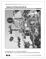
Page 42: ...39 HYDRAULIC FITTING INSTRUCTION 9 Assemble No 20 21 22 23 respectively The orientation is very important so there is no issues with tire fouling 20 21 22 23...

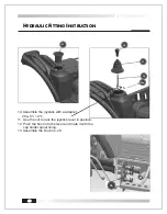
Page 43: ...N 10 Assemble the joystick with a adapter 26a 01 1211 11 Use the nut to lock the joystick lever in position 12 Push the boot into the lever and mate it with the cup holder spout lining 13 Assemble the...

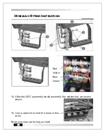
Page 44: ...RAULIC FITTING INSTRUCTION 14 After the QRC assembly kindly assembly the cables ties as shown above 15 Use a cable tie to hold the hose in this area Refer user manual for torque chart Red Yellow Blue...

Page 45: ...ion This document explains wiring connections to te tractor joystick ITEM NO DESCRIPTION QTY 1 ONE PUSHBUTTON JOYSTICK 1 2 NUT PLAIN FINE M14 1 3 SOCKET SCREWSET M8 12 LG 2 4 CONNECTORCABLE 1 ITEM NO...

Page 46: ...d knob Install the Indemar make push button joystick knob on the handle Insert the wire through the rubber boot Connect the joy wire to the wire kit supplied Route the wires to avoid interference with...

Page 47: ...44 HYDRAULIC FITTING INSTRUCTION Assembly images for reference...

Page 48: ...on each side of valve spool to free up spool Contamination in hydraulic oil causes spool to stick Replace oil and filter Solenoid valve section is damaged Replace solenoid valve section Two pin conne...

Page 49: ......

Page 50: ...TM TM...

Reviews: