


48
| Optidrive P2 User Guide |
Version 3.07
www.invertekdrives.com
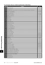
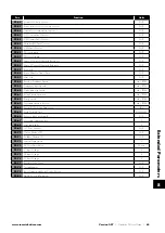
Par
Parameter Name
Minimum
Maximum
Default
Units
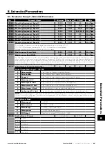
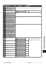
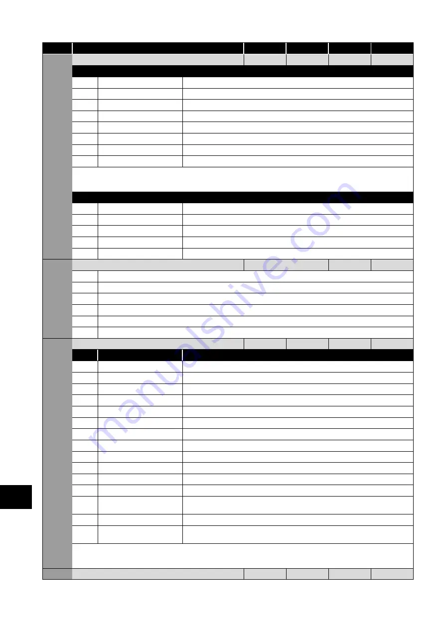
P2-13
Analog Output 2 Function (Terminal 11)
0
12
9
-
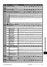
Digital Output Mode. Logic 1 = +24V DC
0
Drive running
Logic 1 when the Optidrive is enabled (Running).
1
Drive healthy
Logic 1 when no Fault condition exists on the drive.
2
At speed
Logic 1 when the output frequency matches the setpoint frequency.
3
Motor speed > 0
Logic 1 when the motor runs above zero speed.
4
Motor speed >= limit
Logic 1 when the motor speed exceeds the adjustable limit.
5
Motor current >= limit
Logic 1 when the motor current exceeds the adjustable limit.
6
Motor torque >= limit
Logic when the motor torque exceeds the adjustable limit.
7
Analog input 2 >= limit
Logic when the signal applied to the Analog Input 2 exceeds the adjustable limit.
NOTE
When using settings 4 – 7, parameters P2-19 and P2-20 must be used together to control the behaviour. The output will switch
to Logic 1 when the selected signal exceeds the value programmed in P2-19, and return to Logic 0 when the signal falls below the
value programmed in P2-20.
Analog Output Mode
8
Motor speed
0 to P1-01.
9
Motor current
0 to 200% of P1-08.
10
Motor torque
0 to 200% of motor rated torque.
11
Motor power
0 to 150% of drive rated power.
12
PID output
Output from the internal PID Controller, 0 – 100%.
P2-14
Analog Output 2 Format
See Below
-
-
-
0 to10V
-
10 to 0V
-
0 to 20mA
-
20 to 0mA
-
4 to 20mA
-
20 to 4mA
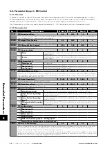
P2-15
Relay 1 Function
0
14
1
-
Setting Function
Logic 1 when
0
Drive running
The Optidrive is enabled (Running).
1
Drive healthy
No fault or trip condition exists on the drive.
2
At speed
Output frequency matches the setpoint frequency.
3
Motor speed > 0
The motor runs above zero speed.
4
Motor speed >= limit
The motor speed exceeds the adjustable limit.
5
Motor current >= limit
The motor current exceeds the adjustable limit.
6
Motor torque >= limit
The motor torque exceeds the adjustable limit.
7
Analog input 2 >= limit
The signal applied to the Analog Input 2 exceeds the adjustable limit.
8
Reserved
No Function.
9
Reserved
No Function.
10
Maintenance due
The internally programmable maintenance timer has elapsed.
11
Drive ready to run
0 to 150% of drive rated power.
12
Drive tripped
The drive is not tripped, the STO circuit is closed, the mains supply is present and the
hardware enable input present (Digital Input 1 unless changed by the user).
13
STO status
When both STO inputs are present and the drive is able to be operated.
14
PID error >= limit
The PID Error (difference between setpoint and feedback) is greater than or equal to the
programmed limit.
NOTE
When using settings 4 – 7 and 14, parameters P2-16 and P2-17 must be used together to control the behaviour. The output
will switch to Logic 1 when the selected signal exceeds the value programmed in P2-16, and return to Logic 0 when the signal falls
below the value programmed in P2-17.
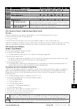
P2-16
Relay 1 / Analog Output 1 Upper Limit
P2-17
200.0
100.0
%
8
Extended P
arameters


