background image

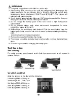
Main Switch 


Tool Operation 

Switch Fixity 

For  safety  concern,  push  forward  switch  fixity  then  press  main  switch  upward  to 
operate the tool. 


Variable Speed Dial


Align the number on the dial with the indication. 
1st Setting RPM

1300 r.p.m. 

2nd Setting RPM

1650 r.p.m. 

3rd Setting RPM

2500 r.p.m. 

4th Setting RPM

3450 r.p.m. 

5th Setting RPM

3800 r.p.m. 


!   WARNING 

1.  Charger is plugged into a 100-240V a.c outlet only. 

2.  If the battery pack is too hot or too cold, the charger will not fast charge the 

battery pack and the red Indicator light is “blinking”. When the battery pack 

temperature returns to between 0

C(32

F) and 50

C(122

F), The charger will 

automatically begin charging. 

3.  If both red and green indicator lights are “ON” the battery pack either does not 

comply or is defective. Please contact your retailer. 

4.  Do  not  charge  the  battery  pack  in  the  rain,  snow  or  high  temperature 

environment. 

5.  Do  not  charge  battery  pack  when  environment  temperature  is  below 

0

C(32

F)or above 40

C(104

F) 

6.  While charge the cool battery pack (below 0

C) in the warm indoor, keep the 

battery pack in the room for one hour to warm up before starting the battery 

pack. 

  A cool battery may charge unsaturated. 

7.  Remove the plug after finishing the charge. 
8.  The charger should be cooled at least one hour after continue charging three 

times. 

9.  Do not use generator for charging the battery pack.


Switch Fixity 

Summary of Contents for EP-1800

Page 1: ...INSTRUCTION MANUAL ITEM NO EP 1800 18V 7 CORDLESS POWER POLISHER EP 1800 I 1403A TE...

Page 2: ...parts mounting and any other condition that may affect its operation 8 A guard or other parts that is damaged should be properly repaired or replaced by an authorized service center unless otherwise i...

Page 3: ...lified service center while repair is required Incorrect reassembling may result in a risk of electric shock or fire Important Safety Instructions for Charger Battery Pack WARNING Additional Safety Ru...

Page 4: ...ort can use large current flow overheating possible burns and even a breakdown 9 Do not store the machine and battery pack in locations where the temperature may reach or exceed 50 C 122 F 10 Do not i...

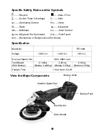
Page 5: ...2 35 kg Battery 0 65kg Charger Time 1 Hour Auto Cut off Battery Pack Battery Knob Main Switch Side Handle Variable Speed Dial Specific Safety Rules and or Symbols Recycle Class II Tool Do Not Throw I...

Page 6: ...pack push the battery knob on the battery pack and pull the battery pack to remove the battery pack from the unit 2 To install the battery pack Push the battery pack into the unit until the battery pa...

Page 7: ...he remaining capacity RC and temperature protection status green LED indications 3 second when the SW button is momentarily pressed Remaining Capacity LED Indication RC Status LED 1 green 0 25 LED 1 2...

Page 8: ...e insert it and try to charge again 7 When you charge a new battery pack or a battery pack which has not been used for a long period it may not accept a full charge This is a normal condition and does...

Page 9: ...between 0 C 32 F and 50 C 122 F The charger will automatically begin charging 3 If both red and green indicator lights are ON the battery pack either does not comply or is defective Please contact yo...

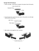
Page 10: ...onge bonnet then replace a new sponge bonnet 2 Cover the lapin cloth put the sponge bonnet on the pad then cover the lapin cloth and tie the cloth strings 3 Side handle is exchangeable to left or righ...

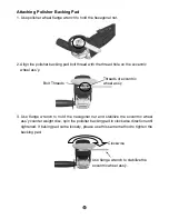
Page 11: ...el ass y 3 Use flange wrench to hold the hexagonal nut and stabilize the eccentric wheel ass y counter weight disc spin the polisher backing pad in clockwise direction until tightened If baking pad ca...

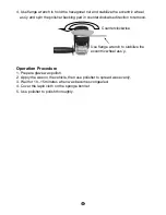
Page 12: ...rection to remove Operation Procedure 1 Prepare glaze wax polish 2 Apply the wax on the vehicle then use polisher to spread wax evenly 3 Wait for 10 15 minutes when wax becomes congealed 4 Cover the l...

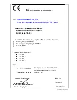
Page 13: ...ies with these normative documents Machinery Directive 2006 42 EC Electromagnetic Compatibility 2004 108 EC RoHS 2011 65 EU Applicable harmonized standard s EN 60745 1 EN 60745 2 3 EN 55014 1 EN 55014...

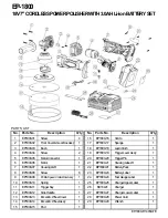
Page 14: ...ng Label R 1 7 EP1800 07 Housing L R 1 22 BP1830L01 Battery Pack 1 8 EP1800 08 Screw 6 23 EP1800 23 Battery Label 1 9 EP1800 09 PCB Speed Control Dial Ass y 1 24 EP1800 24 Fuel Gauge Label 1 10 EP1800...

Page 15: ...NOTE...

Page 16: ...NOTE...

Reviews: