


Section 2
ES-8 MOBILE APPLICATION MANUAL R00
11
INSTALLATION
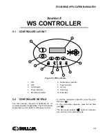
2.1
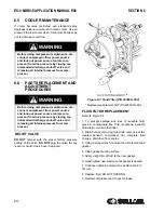
LOCATION OF
COMPRESSOR
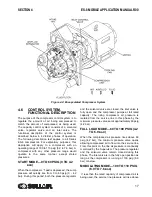
The ES-8 Series compressor package may be
placed on any level surface able to support its
weight. The unit is mounted on vibration mounts and
can be bolted to a fixed mounting surface to avoid
the possibility of externally applied forces or vibration
which would disturb the piping or wiring.
2.2
VENTILATION AND
COOLING
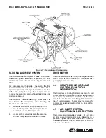
Select a location to permit sufficient unobstructed air
flow in and out of the compressor to keep the
operating temperature stable.
The minimum
distance that the machine should be from
surrounding walls and ceiling is what is needed
for service and three (3) feet (914mm) or more
from the compressor fluid cooler.
2.3
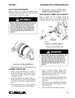
SERVICE AIR PIPING
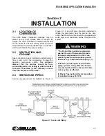
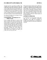
Service air piping should be installed as shown in
. A shut-off valve should be installed to
isolate the compressor from the service line. Also
notice that the service line should be equipped with
water legs and condensate drains throughout the
system.
WARNING
“The Plastic Pipe Institute recommends
against the use of thermoplastic pipe to
transport compressed air or other com-
pressed gases in exposed above ground
locations, e.g. in exposed plant piping.” (I)
Sullube 32 should not be used with PVC
piping systems. It may affect the bond at
cemented joints.Certain other plastic mate-
rials may also be affected.
(I) Plastic Pipe Institute, Recommendation
B, Adopted January 19, 1972.
Figure 2-1: Service Air Piping
Summary of Contents for 30XH
Page 10: ...NOTES 10 ...
Page 22: ...NOTES 22 ...
Page 33: ...NOTES 33 ...
Page 34: ...INLET CONTROL SEAL DRIVE GEAR AND PARTS 34 8 3 INLET CONTROL SEAL DRIVE GEAR AND PARTS ...
Page 36: ...MOTOR COUPLING FAN AND PARTS 36 8 4 MOTOR COUPLING FAN AND PARTS ...
Page 40: ...COMPRESSOR COOLER SYSTEM AND PARTS 40 8 6 COMPRESSOR COOLER SYSTEM AND PARTS ...
Page 42: ...PNEUMATIC CONTROL SYSTEM AND PARTS 42 8 7 PNEUMATIC CONTROL SYSTEM AND PARTS ...
Page 44: ...CONTROL STARTER MFV 44 8 8 CONTROL STARTER MFV ...
Page 46: ...DECAL GROUP 46 8 9 DECAL GROUP ...
Page 48: ...DECAL GROUP 48 8 9 DECAL GROUP CONTINUED ...
Page 50: ...WIRING DIAGRAM FULL VOLTAGE STANDARD 50 8 10 WIRING DIAGRAM FULL VOLTAGE STANDARD ...
Page 51: ...NOTES 51 ...