


Section 5
SUPERVISOR
II
18
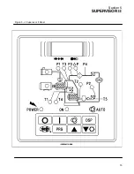
MOTOR
--- If flashing, indicates the motor overload
contact has opened.
INLET FILTER
--- If flashing, indicates that inlet filter
maintenance is needed.
OIL FILTER
--- If flashing, indicates that oil filter
maintenance is needed (oil filter differential pres-
sure dP2 maximum has been reached).
POWER ON
--- Lit if 120VAC power is applied to the
Supervisor II.
ON
--- If lit steady, the compressor is running. If
flashing, indicates that the compressor is armed
but stopped because of restart timer not expired,
remote stop or sequence stop.
The compressor
may start at any time.
AUTO
--- If lit steady, the compressor is running and
in auto mode. If flashing, indicates that the com-
pressor is armed but stopped because of restart
timer not expired, remote stop or sequence stop.
The compressor may start at any time.
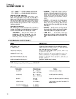
5.5 OPERATING PARAMETER SETUP
Pressing the program key enters parameter dis-
play and edit mode. To move to the next parameter
press the program key. To increment a parameter
press the up arrow key or logo key. The logo key
will increment by 10. To decrement the value press
the down arrow key.
The parameters are displayed in the following or-
der:
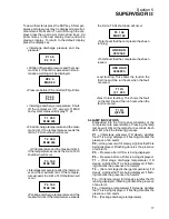
S
Unload pressure
--- The pressure where
the machine is unloaded. For example if
this parameter is set to 110 psi (7.6 bar) the
machine will unload when the line pressure
reaches 110 psi (7.6 bar).
UNLOAD
110 PSI
S
Load differential
--- The pressure differ-
ential below the unload pressure where the
machine is loaded. For example if the un-
load pressure is set to 110 psi (7.6 bar) and
the load differential is set to 10 psid (0.7
bar), the machine will load when the line
pressure goes below 100 psi (6.9 bar).
LOAD
10 PSI
S
P1 Max
--- Maximum oil sump pressure.
An alarm and shut down will occur when
the oil sump pressure rises above this
pressure.
P1 MAX
135 PSI
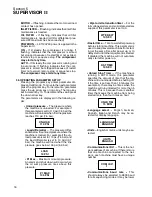
S
Wye to delta transition timer
--- For the
full voltage starters and solid state starters
supplied, this parameter is set to 0.
WYE DELT
10 SEC
S
Restart time
--- Time to wait after powerup
before starting machine. This parameter is
used to keep several machines from start-
ing at the same time after power up, or to
delay start until other equipment is started.
If disabled the machine will not automati-
cally start after power up.
RST TIME
10 SEC
S
Unload Stop Timer
--- If the machine is
running in AUTO mode, this parameter
specifies the amount of time that the ma-
chine will run unloaded before shutting off.
If the time is set less than 15 minutes (for
example 5), there may be times when the
machine will run unloaded for more than 5
minutes. This is because there is another
timer that keeps the machine from being
started more than four times an hour.
UNLD TIM
15 MIN
S
Language select
--- English, German,
Spanish, Italian and French may be se-
lected for display language.
LANGUAGE
ENGLISH
S
Units
--- English or metric units may be se-
lected.
UNITS
ENGLISH
S
Communications ID #
--- This is the net-
work address of a machine. If there is more
that one machine connected to the net-
work, each machine must have a unique
number
COM ID #
1
S
Communications baud rate
--- This
should always be selected to 9600 baud
for all sequencing modes. It may be lower
Summary of Contents for DR-13 Series
Page 6: ...NOTES ...
Page 14: ...8 NOTES ...
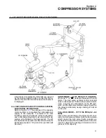
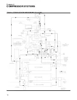
Page 18: ...Section 4 COMPRESSOR SYSTEMS 12 Figure 4 5 Piping and Instrumentation Diagram Air cooled ...
Page 21: ...Section 5 SUPERVISOR II 15 Figure 5 1 Supervisor II Panel ...
Page 28: ...22 NOTES ...
Page 32: ...26 NOTES ...
Page 42: ...Section 7 MAINTENANCE 36 Table 1 Installation Data ...
Page 46: ...40 NOTES ...
Page 48: ...Section 9 ILLUSTRATIONS AND PARTS LIST 42 9 3 COMPRESSOR MOTOR AND FRAME ...
Page 50: ...Section 9 ILLUSTRATIONS AND PARTS LIST 44 9 4 AIR INLET SYSTEM ...
Page 52: ...Section 9 ILLUSTRATIONS AND PARTS LIST 46 9 5 COOLER ASSEMBLY ...
Page 54: ...Section 9 ILLUSTRATIONS AND PARTS LIST 48 9 6 LP HOT LP COLD ...
Page 56: ...Section 9 ILLUSTRATIONS AND PARTS LIST 50 9 7 HP DISCHARGE ...
Page 58: ...Section 9 ILLUSTRATIONS AND PARTS LIST 52 9 8 LUBE SYSTEM ...
Page 60: ...Section 9 ILLUSTRATIONS AND PARTS LIST 54 9 9 ELECTRICAL BOX ...
Page 62: ...Section 9 ILLUSTRATIONS AND PARTS LIST 56 9 10 CONTROL SYSTEM CONDENSATE DRAIN ...
Page 64: ...Section 9 ILLUSTRATIONS AND PARTS LIST 58 9 11 CANOPY ...
Page 66: ...Section 9 ILLUSTRATIONS AND PARTS LIST 60 9 12 DECALS ...
Page 68: ...Section 9 ILLUSTRATIONS AND PARTS LIST 62 9 12 DECALS ...
Page 70: ...Section 9 ILLUSTRATIONS AND PARTS LIST 64 9 12 DECALS ...
Page 72: ...Section 9 ILLUSTRATIONS AND PARTS LIST 66 9 13 DECAL LOCATIONS ...
Page 74: ...Section 9 ILLUSTRATIONS AND PARTS LIST 68 9 13 DECAL LOCATIONS ...
Page 76: ...Section 9 ILLUSTRATIONS AND PARTS LIST 70 9 13 DECAL LOCATIONS ...
Page 78: ...Section 9 ILLUSTRATIONS AND PARTS LIST 72 9 14 WIRING DIAGRAM ...
Page 79: ...NOTES ...


