


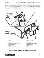


SECTION 2
300HH, 375, 375H, 375HH, 425 AND 425H USER MANUAL R00
19
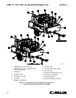
The control system can easily be adjusted for
pressures from 80 to 125 psig (5.6 to 8.6 bar) for
standard machines, from 80 to 150 psig (5.6 to 10.3
bar) for “H” machines and from 80 psig to 200 psig
(5.6 to 13.8 bar) for “HH” machines. The compressor
unit is driven by an industrial diesel engine designed
to provide enough horsepower to provide an
adequate reserve under rated conditions.
Refer to the
Engine Operator’s Manual
for a more
detailed description of the engine. The engine
cooling system is comprised of a radiator, charge air
cooler, high capacity fan, and thermostat. The high
capacity fan pushes air through the radiator to
maintain the engine’s specified operating
temperature. The same fan also cools the fluid in the
compressor cooling and lubrication system.
The engine radiator, charge air cooler, and the
compressor fluid cooler are next to each other
allowing the fan air to push through all three
simultaneously. As air passes through the fluid
cooler, the heat of compression is removed from the
fluid. The compressor’s high capacity fuel tank
contains enough fuel for one eight hour shift under
normal operating conditions.
2.3
SULLAIR COMPRESSOR
UNIT, FUNCTIONAL
DESCRIPTION
Sullair compressors are single-stage, positive
displacement, flood lubricated-type compressors that
provide continuous (pulse-free) compression to meet
various demand loads. Sullair compressors require
no routine maintenance or inspection of their internal
parts or systems. The compressor works by injecting
fluid into the compressor unit where it mixes directly
with the air as the rotors turn: the rotor’s rotation
compresses the air. The fluid flow has three main
functions:
1. It acts as a coolant, to control the rise of air
temperature which is generated by compres-
sion (heat of compression).
2. Seals the leakage paths between the rotors
and the stator and also between the rotors
themselves.
3. Lubricates the rotors allowing one rotor to
directly drive the other.
After the air fluid mixture is discharged from the
compressor unit, the fluid is separated from the air.
At this time, the air flows to the service line and the
fluid is cooled in preparation for re-injection.
2.4
COMPRESSOR COOLING
AND LUBRICATION
SYSTEM, FUNCTIONAL
DESCRIPTION
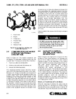
. The compressor cooling and
lubrication system is designed to provide adequate
lubrication as well as maintain the proper operating
temperature of the compressor. In addition to the
fluid cooler and interconnecting piping, the system
consists also of three other components: a fluid filter,
thermal valve, and a fan which perform the following
functions:
• The fluid filter removes and collects any contami-
nants in the fluid.
• The thermal valve functions as a temperature regu-
lator directing fluid either to the cooler or to the
compressor unit.
• The fan pushes air through the cooler dissipating
the heat resulting from compression of the fluid.
The functions of the lubrication system are explained
in more detail below. Fluid is used in the system as a
coolant and as a lubricant: the sump serves as the
fluid reservoir. At start-up, fluid flows from the sump
to the fluid thermal valve. Fluid circulation is achieved
by forcing the fluid from the high pressure region of
the sump to a lower pressure area in the compressor
unit. A minimum pressure device (See
Discharge System, Functional Description
20) is provided to assure adequate fluid flow under
all conditions. When entering the thermal valve upon
start-up, the fluid temperature is cool and thus it is
not necessary to route it through the cooler. The fluid
flows through the fluid filter and on to the compressor
unit bypassing the cooler. As the compressor
continues to operate, the temperature of the fluid
rises and the thermostatic control opens, allowing a
portion of the fluid into the cooler.
When the temperature reaches 155°F (68°C), the
thermostat is fully open allowing all fluid entering the
thermal valve to flow to the cooler.
The cooler is a radiator type that works in concert
with the engine fan. The fan pushes air through the
cooler removing the heat from the fluid. From the
cooler, the fluid is then routed back through the fluid
filter. All fluid flowing to the compressor unit passes
through this filter. The fluid leaving the filter flows to
the compressor unit where it lubricates, seals and
cools the compression chamber; and lubricates the
bearings and gears.
Summary of Contents for 300HH
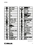
Page 17: ...SECTION 1 15 Safety Symbols 2 ...
Page 18: ...SECTION 1 16 Safety Symbols 3 ...
Page 49: ...SECTION 2 300HH 375 375H 375HH 425 AND 425H USER MANUAL R00 47 2 9 WIRING DIAGRAM ...
Page 60: ...NOTES 58 ...
Page 79: ...NOTES ...