


Section 2
DESCRIPTION
16
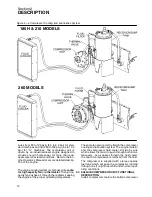
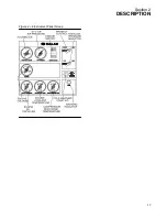
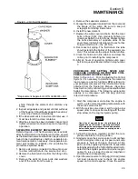
Figure 2---5 Air Inlet System (typical)
provided to shut down the compressor when the en-
gine oil pressure becomes insufficient. The low
speed switch is provided to shutdown the compres-
sor if engine speed falls below 1500 RPM.
2.10 SHUTDOWN SYSTEM DESCRIPTION
The Shutdown System and Annunciation Module
(SSAM) continually monitors the status of the com-
pressor . In the event of a shutdown condition, the
SSAM will shutdown the compressor and flash the
appropriate code on the instrument panel annun-
ciator light. The flash code will remain active (flash-
ing) until the ignition switch is turned OFF. The flash
codes are as follows:
1 flash : high compressor temperature
2 flashes: high engine coolant temperature
3 flashes: low engine oil pressure
4 flashes: low engine speed
5 flashes: low fuel level (optional)
The SSAM also provides startup logic for the com-
pressor. When the ignition switch is placed in the
ON position, the annunciator light will come on for
30 seconds. During this 30 second period, ignition
switch activation to the START position will engage
the engine starter. The low engine oil pressure
switch and the low engine speed switch will remain
inactive during the this 30 second period. At the end
of the 30 second period, the annunciator light will
go off and the engine START cycle will be disabled.
At this time, all safety system checks become ac-
tive including low fuel level (if equipped).
Summary of Contents for 185H
Page 6: ......
Page 14: ...8 NOTES...
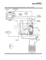
Page 20: ...Section 2 DESCRIPTION 14 Figure 2 4B Control System with Piping and Instrumentation 260 Models...
Page 23: ...Section 2 DESCRIPTION 17 Figure 2 6 Instrument Panel Group...
Page 24: ...Section 2 DESCRIPTION 18 Figure 2 7 Electrical System JOHN DEERE 02250144 446R05...
Page 25: ...Section 2 DESCRIPTION 19 Figure 2 7A Electrical System CATERPILLAR P02250144 395R04...
Page 26: ...20 NOTES...
Page 30: ...24 NOTES...
Page 36: ...Section 5 MAINTENANCE 30 Figure 5 4 Control System Adjustment 185H 210 MODELS 260 MODELS...
Page 42: ...36 NOTES...
Page 49: ...Section 7 ILLUSTRATIONS AND PARTS LIST 43 NOTES...
Page 90: ...Section 7 ILLUSTRATIONS AND PARTS LIST 84 7 10 ELECTRICAL PARTS ALL MODELS 02250148 897R00...
Page 128: ...Section 7 ILLUSTRATIONS AND PARTS LIST 122 7 20 DECALS...
Page 130: ...Section 7 ILLUSTRATIONS AND PARTS LIST 124 7 20 DECALS...
Page 132: ...Section 7 ILLUSTRATIONS AND PARTS LIST 126 7 20 DECALS...
Page 134: ...Section 7 ILLUSTRATIONS AND PARTS LIST 128 7 20 DECALS...
Page 136: ...Section 7 ILLUSTRATIONS AND PARTS LIST 130 7 20 DECALS...
Page 138: ...Section 7 ILLUSTRATIONS AND PARTS LIST 132 7 21 DECAL LOCATIONS 02250149 633R01...
Page 142: ......
Page 143: ......


