background image

36

 EN/06.2016/i01   © STULZ S.p.A. – all rights reserved

WPA ExPlOrEr OrIGINAl INSTrUCTIONS

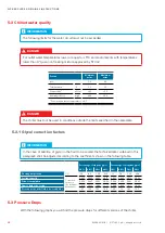
5.2 Chilled water quality

  INFOrMATION

The following limits for the water circuit must not be exceeded


DANGEr

For outlet water temperatures lower or equal to +5°C and environments with temperatures 
lower than 0°C, use non freezing mixture approved by STULZ

Feature

Minimum 

value

Maximum 

value

pH

(*)

7,0

8,0

Total hardness

(*)

°F

13

35

Conductivity

(*)

µS/cm

200

350

Alcalinity (HCO3)

(*)

mg/L

200

300

(*)

 Considering water at tempe20°C


DANGEr

The chiller must not be used in conditions outside the limits specified in the nameplate

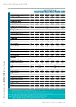
5.2.1 Glycol correction factors

  INFOrMATION

In the case of addition of glycol in the fluid to be cooled, the technical data contained in this 
paragraph shall be adjusted according to the coefficients shown in the following table.

Percentage of ethylene glycol

Percentage of propylene glycol

10%

20%

30%

40%

10%

20%

30%

40%

Freezing temperature

[°C]

-3.9

-8.9

-15.6

-23.4

-3.3

-7.8

-12.2

-20.6

Cooling capacity

Correction 
factors on 
the technical 
data sheets

0.997

0.990

0.984

0.977

0.993

0.985

0.974

0.962

Power consumption

0.999

0.997

0.996

0.994

0.999

0.996

0.993

0.989

Flow of fluid to be cooled

1.014

1.033

1.068

1.117

0.989

1.009

1.017

1.040

Pressure drop on the fluid to be cooled side

1.07

1.16

1.30

1.48

1.04

1.14

1.23

1.37

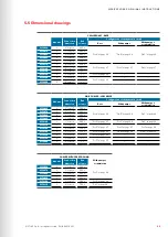
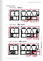
5.3 Pressure Drops

With the following graphs you will find the pressure drops for different versions of the chiller.

Summary of Contents for Explorer WPA

Page 1: ...Index i01 Issue 06 2016 WPA Explorer Original instructions Air cooled liquid chillers 400V 3 50Hz...

Page 2: ...nd from many thousands of projects that we have implemented worldwide We have systems and solutions of all sizes and with the most diverse requirements take advantage of our know how Founded in Hambur...

Page 3: ...chiller The CE mark guarantees that the STULZ products fulfill the requirements of the European Machinery Directive for safety The level of quality is permanently checked at every phase from design to...

Page 4: ...15 3 2 Storage 16 3 3 Transport 16 3 3 1 Transport protection 16 3 3 2 Centre of gravity 18 4 Description 20 4 1 Type Code 20 4 2 Intended use 21 4 3 Chiller Design 21 4 3 1 General 21 4 3 2 Versions...

Page 5: ...Commisioning 63 7 1 Preparation 63 7 2 First Startup 63 7 2 1 Oil preheating 64 7 2 2 Commissioning of the chilled water circuit 64 7 2 3 Commissioning of the refrigerant circuit 65 8 Maintenance 67...

Page 6: ...e warranty is limited to free replacement and shipping of any faulty part or sub assembly which has failed due to poor quality or manufacturing errors All claims must be supported by evidence that the...

Page 7: ...ntet of the chiller Location next to the inlet fitting of the hydraulic circuit Exit of the hydraulic circuit of the chiller outlet of the chiller Location next to the outlet fitting of the hydraulic...

Page 8: ...LIQUIDE SERIE SERIES SERIE SERIE DATA DATE DATUM DATE WPAR044207ZFT0 7035 N 0000408788 07 11 12 MODELLO MODEL TYP MODELE MADE IN ITALY ORDINE ORDER ORDER COMMANDER 2120002673 10 C TS MIN Refrigerante...

Page 9: ...ng on it The unit must be earthed WARNING The unit may only be used to cool water according to the Stulz specification Observe the national regulations of the country where the unit will be installed...

Page 10: ...ment and inspection before the delivery also the opera tor of such plants has duties according to EN 378 and national regulations This concerns the installation the operation and the repeated inspecti...

Page 11: ...e converted or modified after consultation with STULZ Original replace ment parts and replacement parts accessories authorised by STULZ are an aid to safety Unacceptable operating methods The operatin...

Page 12: ...rigerant piping closed stop valves defective safety valve Discharge of refrigerant under high pressure burns in case of contact to the skin formation of acid vapours with open flames Open stop valves...

Page 13: ...antling Area Danger Risk Preventative measures Refrigerant piping Soldering off or cutting the refrigerant pipes still under pressure Discharge of refrigerant under high pressure burns in case of cont...

Page 14: ...SAN CO LTD 3 1 1 MarunouchI Chiyoda Ku Tokyo Japan 2 Hazards identification Hazard Classification Toxic fumes may be released in case of fire Firefighters should wear full protective clothing and self...

Page 15: ...be nitrogen The chiller units must always be transported upright INFORMATION The refrigerant circuit is filled with R410A refrigerant ready to use The chiller is labelled as follows STULZ Logo STULZ o...

Page 16: ...mage A periodic inspection is highly recommended If your chiller contains refrigerant gas during the storage period you also have to consider the current F Gas regulations and EN 378 3 3 Transport The...

Page 17: ...17 STULZ S p A all rights reserved EN 06 2016 i01 WPA Explorer ORIGINAL INSTRUCTIONS Spacer Rope Shakles Lifting bar with stop end...

Page 18: ...1040 mm 1040 mm 1050 mm 1050 mm 1050 mm z 980 mm 980 mm 990 mm 990 mm 980 mm F C 1 pump tank WPA 060 WPA 070 x 1170 mm 1200 mm y 1150 mm 1220 mm z 960 mm 930 mm Base without pump without tank WPA 110...

Page 19: ...thout pump without tank WPA 140 WPA 160 WPA 180 WPA 200 x 1270 mm 1260 mm 1270 mm 1270 mm y 2060 mm 2640 mm 2230 mm 2230 mm z 1070 mm 1000 mm 940 mm 940 mm Low Noise without pump without tank WPA 180...

Page 20: ...kW 1 090 245 kW 1 160 432 kW 1 100 266 kW 1 180 504 kW 1 1 at 50 Hz W7L35 200 559 kW 1 S 7 digit Type of compressor and refrigerant S Scroll compressors R410A 8 digit C Version C chiller D chiller wit...

Page 21: ...ons The standard version for air cooled chillers with scroll compressors has a unit designation which takes the following pattern WPA _ _ _ SCN _ There are two more versions which will be described in...

Page 22: ...arm signal is shown on the electronic control display The pressure switch needs to be reset manually High pressure switch A high pressure switch is installed in each cooling circuit It will be activat...

Page 23: ...or each refrigerant circuit For each circuit high and low pressure switch to guarantee the safety high and low pressure transducer to manage the compressors EEV and fans sensor for discharge and sucti...

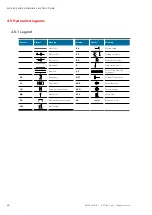
Page 24: ...t off valve DP LP HP PV PD Needle valve RL DP LP HP PV PD Liquid receiver BC DP LP HP PV PD Condenser S DP LP HP PV PD Temperature transmitter CO DP LP HP PV PD Compressor SG DP LP HP PV PD Solenoid V...

Page 25: ...01 WPA Explorer ORIGINAL INSTRUCTIONS Not present in 060 070 models Standard circuit diagram Check MANUAL PART IIa for any changes WPA 060 070 080 090 100 110 120 140 160 180 200 Base Low noise Free c...

Page 26: ...ONS BC3 BC4 present only on models 100 low noise 110 all versions 120 all versions 140 all versions Standard circuit diagram Check MANUAL PART IIa for any changes WPA 060 070 080 090 100 110 120 140 1...

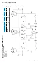
Page 27: ...r compressors four condensing modules Standard circuit diagram Check MANUAL PART IIa for any changes WPA 060 070 080 090 100 110 120 140 160 180 200 Base Low noise Free cooling RL1 RL2 only present on...

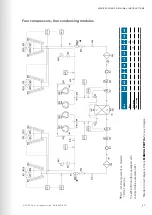
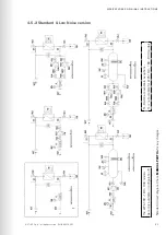
Page 28: ...ved WPA Explorer ORIGINAL INSTRUCTIONS Six compressors four condensing modules Shell and tube evaporator EV Standard circuit diagram Check MANUAL PART IIa for any changes WPA 060 070 080 090 100 110 1...

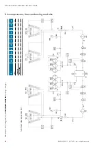
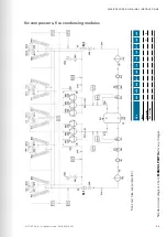
Page 29: ...i01 WPA Explorer ORIGINAL INSTRUCTIONS Six compressors five condensing modules Standard circuit diagram Check MANUAL PART IIa for any changes WPA 060 070 080 090 100 110 120 140 160 180 200 Base Low n...

Page 30: ...t RU RE AB A B Water shut off valve RE AB A B Water tank S DP LP HP PV PD Temperature sensor RE AB A B Manifold SC DP LP HP PV PD Free cooling water air exchanger EV RE AB A B Evaporator VICT RE AB A...

Page 31: ...RIGINAL INSTRUCTIONS The WPA 160 180 200 models were only available in configuration 1 FL RA RE are available as options FL is not available for WPA 160 180 200 models Standard circuit diagram Check M...

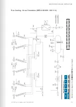
Page 32: ...PA Explorer ORIGINAL INSTRUCTIONS Free Cooling two V modules WPA 060 070 FL RA RE on the storage tank available as options The WPA 160 180 200 models were only available in configuration 1 Standard ci...

Page 33: ...plorer ORIGINAL INSTRUCTIONS Free Cooling three V modules WPA 080 090 100 110 FL RA RE on the storage tank available as options Standard circuit diagram Check MANUAL PART IIa for any changes QUICK COU...

Page 34: ...igh pressure limiter 40 5 barg Low pressure switch 2 4 barg High pressure safety valve 45 barg Type of network TT TN S TN C S Voltage 400 V 3ph 50Hz PE Voltage Tolerance 10 Frequency Tolerance 1 Rated...

Page 35: ...PA090 57 54 51 45 10 10 10 WPA100 57 54 50 43 10 10 10 WPA110 58 57 54 48 6 10 10 WPA120 57 5 55 51 5 45 5 8 10 10 WPA140 57 53 5 51 44 10 10 10 WPA160 57 5 56 52 5 47 7 10 10 WPA180 55 51 50 5 43 5 1...

Page 36: ...orrection factors INFORMATION In the case of addition of glycol in the fluid to be cooled the technical data contained in this paragraph shall be adjusted according to the coefficients shown in the fo...

Page 37: ...0 W P A 0 7 0 W P A 0 6 0 W P A 0 6 0 W P A 0 7 0 W P A 0 8 0 W P A 0 9 0 W P A 1 0 0 W P A 1 1 0 37 STULZ S p A all rights reserved EN 06 2016 i01 WPA Explorer ORIGINAL INSTRUCTIONS Water flow m h P...

Page 38: ...0 6 0 W P A 0 7 0 W P A 0 8 0 W P A 0 9 0 W P A 1 0 0 W P A 1 1 0 W P A 1 2 0 W P A 1 4 0 38 EN 06 2016 i01 STULZ S p A all rights reserved WPA Explorer ORIGINAL INSTRUCTIONS Water flow m h Pressione...

Page 39: ...0 7 0 W P A 0 8 0 W P A 0 9 0 W P A 1 0 0 W P A 1 1 0 W P A 1 2 0 W P A 1 4 0 39 STULZ S p A all rights reserved EN 06 2016 i01 WPA Explorer ORIGINAL INSTRUCTIONS Water flow m h Water flow m h Pressio...

Page 40: ...ent consumption A 82 3 100 4 108 6 122 7 137 9 Maximum current consumption A 132 154 176 194 212 Fans No 0 4 4 4 4 4 Air flow with free outlet m h 57600 57600 85500 85500 85500 Power consumption kW 3...

Page 41: ...8 3 Maximum volume of water in the system dm 19 5 n a n a n a Tank volume if provided l 750 n a n a n a Refrigerant Circuit Refrigerant R410A Refrigerant charge per circuit kg 22 5 25 24 5 69 80 5 89...

Page 42: ...34 0 Maximum volume of water in the system dm 13 Tank volume if provided l 500 Refrigerant Circuit Refrigerant R410A Refrigerant charge per circuit kg 18 17 5 17 18 15 5 No of refrigerant circuits 2...

Page 43: ...19 5 n a n a n a Tank volume if provided l 750 n a n a n a Refrigerant Circuit Refrigerant R410A Refrigerant charge per circuit kg 22 5 25 24 5 69 80 5 89 No of refrigerant circuits 2 2 2 2 2 2 Oil c...

Page 44: ...power supply V Hz 400 3 50 Maximum power consumption kW 90 4 103 2 118 6 135 27 143 2 159 4 Maximum current consumption A 161 3 183 3 213 1 234 2 252 2 283 3 Inrush current A 282 3 349 3 379 1 391 2...

Page 45: ...s Tank volume Configuration of the hydraulic circuit Base With pumps With pumps accumulation WPA060 2 3 Victaulic 500 L Dis A at page 46 Dis B at page 46 Dis C at page 46 WPA070 2 3 Victaulic 500 L WP...

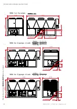
Page 46: ...ights reserved WPA Explorer ORIGINAL INSTRUCTIONS Without pump With 1or 2 pumps With 1or 2 pumps tank Dis A Dis B Dis C 2V shapes modules Standard layout Check MANUAL PART IIa for any changes Standard...

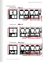
Page 47: ...Victaulic IN OUT 47 STULZ S p A all rights reserved EN 06 2016 i01 WPA Explorer ORIGINAL INSTRUCTIONS Without pump With 1or 2 pumps Without pump Dis D Dis G Dis H 3V shapes modules Standard layout Che...

Page 48: ...IN OUT 48 EN 06 2016 i01 STULZ S p A all rights reserved WPA Explorer ORIGINAL INSTRUCTIONS With 1 or 2 pumps With 1or 2 pumps tank With 1or 2 pumps tank Dis E Dis F Dis I Standard layout Check MANUA...

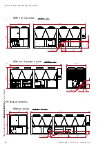
Page 49: ...5 2406 411 2200 5 Victaulic IN OUT 49 STULZ S p A all rights reserved EN 06 2016 i01 WPA Explorer ORIGINAL INSTRUCTIONS Without pump Without pump Without pump Dis L Dis O Dis P 4V shapes modules Stand...

Page 50: ...28 328 2406 2208 4 Victaulic IN OUT 50 EN 06 2016 i01 STULZ S p A all rights reserved WPA Explorer ORIGINAL INSTRUCTIONS With 1 or 2 pumps With 1or 2 pumps tank Without pump Dis M Dis N Dis Q 5V shape...

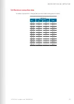
Page 51: ...tch and signals connector Input lug size Model General lock door Signal Base Free Cooling WPA 060 M10 M10 Mini fit WPA 070 M10 M10 Mini fit WPA 080 M10 M10 Mini fit WPA 090 M10 M10 Mini fit WPA 100 M1...

Page 52: ...ke place and a high sun exposure is present For locations where outer influences might affect the airflow an enclosure or louvre is recom mended Please consider negative impacts on the airflow by near...

Page 53: ...m 1 25 m 2 5 m 2 5 m 1 8 m 1 8 m 0 7 m 1 25 m 1 25 m 53 STULZ S p A all rights reserved EN 06 2016 i01 WPA Explorer ORIGINAL INSTRUCTIONS 6 1 1 Minimum distance from obstacles or other chillers 6 1 2...

Page 54: ...0 090 Free Cooling WPA 060 070 P1 P2 P3 P4 Without pump without tank 24 37 24 15 With pump without tank 24 37 24 15 With pump with tank 23 35 26 16 P1 P2 P3 P4 P5 P6 Without pump without tank 23 23 15...

Page 55: ...160 180 200 Low Noise WPA 140 160 Low Noise WPA 180 200 P1 P2 P3 P4 P5 P6 P7 P8 Without pump without tank 19 19 8 13 13 8 14 8 With pump without tank 19 19 8 13 13 8 14 8 With pump with tank 8 17 15...

Page 56: ...f a motor driven 3 way control valve and another temperature sensor in the chilled water circuit For a detailed overview please take a look at the circuit dia gram in chapter 4 5 Hydraulic diagrams at...

Page 57: ...ly Circulating pump with sufficient delivery height according to the minimum and maximum flow rates and corresponding pressure drop which can be found in chapter 5 4 Technical Data at page 30 Expansio...

Page 58: ...pipe compensators in the chilled water inlet and outlet are recommended Inlet Outlet Inlet Outlet Symbol Meaning Symbol Meaning Water line Pipe compensator Water shut off valve Mesh strainer If you c...

Page 59: ...mend the following good practice install a water bypass to be able to carry out work at the chiller without having to disconnect it from the pipework connect the pipe with adequate supports so that it...

Page 60: ...nnect filling hoses to the vent valves to catch the discharging mixture and dispose of it separately WARNING Once the circuit is filled the freeze protection function is essential Check if the circula...

Page 61: ...the wires can be adjusted within the range of the panel shown in the following views 7mm triangular key Cuttable removable pannel Front side The power supply system on site and the pre fuses must be...

Page 62: ...onic control board provides digital outputs for alarm signals and status of the unit The assignment of outputs to different alarms and status data can be configured in the controller unit The default...

Page 63: ...ing to the outside temperature of the refrigerant pressure In case off leak age please contact the manufacturer Check the fans Be sure that the fan guards are all correctly installed and the fans are...

Page 64: ...er requires an oil preheating time of 24 hours During the oil preheating time the compressor cabinet should be kept closed 7 2 2 Commissioning of the chilled water circuit WARNING Ensure that the wate...

Page 65: ...erify by reading the pres sures that the saturation temperatures for evaporation low pressure side and condensation high pressure side which correspond to the measured pressures are within the followi...

Page 66: ...xplorer ORIGINAL INSTRUCTIONS Compressor operation According to the compressors manufacturer specifications the following preset paramenters must be kept Value description Time Minimum runtime of comp...

Page 67: ...verifications must be effected with the unit in operation measuring the current pressures temperatures In such a case the unit must only be switched on at the master switch after all mechanical conne...

Page 68: ...abnormal vibration Check the absence of abnormal noise The maintenance must be performed when necessary in order to ensure the smooth operation of the chiller 8 3 Refrigerant Circuit 8 3 1 Refrigeran...

Page 69: ...mpanies or persons which have carried out maintenance dates and results of inspections 8 3 4 Purity To be checked sight glass filter drier At full cooling capacity bubbles in the sight glass indicate...

Page 70: ...wise reduces the action value A check of the tripping function of the high pressure limiter e g by cutting down the condenser fan and forcing a high Adjustment screw Adjustment lock HP switch with res...

Page 71: ...o deviation at the verifications probably the control module of the valve is defective and must be replaced The expansion valve can freeze if the humidity in the refrigerant circuit is excessive Check...

Page 72: ...the exchange efficiency and increase the pressure drop on the air side Do not use chemicals these could cause corrosion at the coils 8 4 2 Condenser Fan To be checked fans The bearings of the fans ar...

Page 73: ...ifreeze heater in the evaporator the water glycol mix ture must be evacuated and collected 8 5 3 Differential pressure switch To be checked differential pressure switch Check the correct function of t...

Page 74: ...e to the thermal breaker of the X fan Replace the protection device Pump X thermic X pump failure Replace the pump Failure of the power supply circuit of the X pump cables remote control switch Replac...

Page 75: ...the display Contact the Stulz service centre Low amount of fluid to be cooled Check the fluid level in the storage tank and if necessary top up Low min temperature Low flow of fluid to be cooled Check...

Page 76: ...the cooling gas into the atmosphere The cooling gas must be recovered by a qualified refrigerator technician and if not reused sent to an authorized disposal centre Even the PVE oil of the compressor...

Page 77: ...bers declare under our own responsibility that this unit is in conformity with Directives 2004 108 CE Electromagnetic compatibility 2006 42 CE Machinery directive 97 23 CE Directives PED PED Category...

Page 78: ...39 045 6331615 aftersales stulz it OTHER AREAS on www stulz com EN 06 2016 i01 STULZ S p A Subjet to change without notice Maintenance Test Center Advice Service Portal Technical Implementation Clima...

Reviews: