background image

Studio Electronics Boomstar Manual

Table of Contents 

iii

1)  The Design Behind the ‘Stars . . . . . . . . . .  1

2)    Setup  Essentials  . . . . . . . . . . . . . . . . . . . . .   2-6

2.1  Warnings, Precautions and Advice ........... 2-4

2.2  Product Registration ............................. 4

2.3  Smart and Safe Connections .................... 5

2.4  Boomstar Warming and Output Warning ..... 6

3)    Signal  Flow  Chart  . . . . . . . . . . . . . . . . . . . . . . .   7

3.1  A Tim Caswell Original ............................ 7

4)    Patch  Reset  . . . . . . . . . . . . . . . . . . . . . . . . . . . . . .   8

4.1  Sawtooth Bass Patch - Factory Reset ........... 8

5)    Panels  . . . . . . . . . . . . . . . . . . . . . . . . . . . . . . . .   9-21

5.1  Front Panel ..................................... 9-10


5.1.1  Adjustment Holes 

..........................


9-10


5.1.1.1  CV input tracking adjust. ............... 9


5.1.1.2  Oscillator 1 high tune adjust............


9


5.1.1.3  Oscillator 1 octave adjust


..............


9


5.1.1.4  Oscillator 1 initial tune adjust .........


9


5.1.1.5  Oscillator 1 scale adjust


................


9


5.1.1.6  Oscillator 2 scale adjust ................


9


5.1.1.7  Oscillator 2 initial tune adjust .........


9


5.1.1.8  Oscillator 2 high tune adjust .........


10


5.1.1.9  Oscillator 2 octave adjust .............


10


5.1.1.10  Envelope Drive .......................


10 


5.1.1.11  VCA Offset .............................


10


5.1.1.12  VCA DC Balance ......................


10

5.2  Top Panel ..................................... 11-19


5.2.1  SEM Controls 

.................................. 

11 


5.2.2  SE80 and 700 Controls 

.......................

 11


5.2.3  Patch Points 

...............................

 11-12


5.2.3.1  CV IN - Control Voltage In


.............


11


5.2.3.2  GATE IN - Gate Input


..................


11


5.2.3.3  VCF FM - VCF Frequency Mod In ..... 11


5.2.3.4  VCA AM - VCA Amplitude Mod In ....


11


5.2.3.5  OSC Out - Oscillator Output


..........


11


5.2.3.6  EXT IN - External Input


................


12 


5.2.4  VCO 1 - Voltage Controlled OSC 1

 ......... 

13


5.2.5  VCO 1 - Voltage Controlled OSC 2

 ......... 

14


5.2.6  VCF - Voltage Controlled Filter 

..........


14-15


5.2.7  ENV 1 - Envelope 1

 ........................ 

15-16


5.2.8  ENV 2 - Envelope 2

 ........................... 

16 


5.2.9  X MOD - Cross Modulation

 .................. 

17


5.2.10  LFO - Low Frequency Oscillator

 ....... 

17-18


5.2.11  VCA - Voltage Controlled Amplifier

 ....... 

18


5.2.12  Master Tune 

..................................


18


5.2.13  Bend

 ........................................... 

18


5.2.14  Glide 

...........................................


18


5.2.15  Dynamics 

.....................................


19


5.2.16  ENV 1 • PW 1 - Envelope 1 to Pulse Wdth


19


5.2.17  MIXER 

..........................................


19


5.2.17.1  VCO 1 - Voltage Cont. OSC 

......... 

19


5.2.17.2  VCO 2 - Voltage  Cont. OSC 2 

....... 

19


5.2.17.3  Ring Mod - Ring Modulation 

........ 

19


5.2.17.4  Noise 

.................................. 

19


5.2.17.5  Feedback

 ............................. 

19

5.3  Back Panel .................................... 20-21


5.3.1  Connections, Switches, Warnings

 .....


20-21


5.3.1.1  Audio Out ............................... 20


5.3.1.2  MIDI ..................................... 20


5.3.1.3  Power Adapter Connection ..........


20

5.4  Side Panel ........................................ 21


5.4.1  Rack Mounting Holes 

........................


21

6)    Legal  . . . . . . . . . . . . . . . . . . . . . . . . . . . . . . . .   22-23

6.1  Liability ........................................... 22

6.2  FCC ............................................. 22-23

6.2  Canada ............................................ 23

6.4  Europe ............................................ 23

7)    Glossary  . . . . . . . . . . . . . . . . . . . . . . . . . . . . . . . .   24

8)    Filter Talkers  . . . . . . . . . . . . . . . . . . . . . . . . . . .   25

8.1  Bace ............................................... 25

8.2  Drew Neumann .................................. 25

9)  The Ancient Chinese . . . . . . . . . . . . . . . . . .  26

10)    Back  Panel Art  . . . . . . . . . . . . . . . . . . . . . . . .   27

11)   Troubleshooting  . . . . . . . . . . . . . . . . . . . . . .   28

12)    Blank  Patch  Sheet  1  . . . . . . . . . . . . . . . . . .   29

13)    Blank  Patch  Sheet  2  . . . . . . . . . . . . . . . . . .   30

BOOMSTAR OPERATION MANUAL

Summary of Contents for BOOMSTAR

Page 1: ......

Page 2: ...e refused and returned Shipping insurance is optional but highly recommended ANALOGIA INC STUDIO ELECTRONICS will repair or replace this product at its sole option and at no charge to you for parts and labor when deemed necessary and within the warranty period provided that ANALOGIA INC STUDIO ELECTRONICS reserves the right to determine whether the product is defective for purposes of this Limited...

Page 3: ...ject to change without notice and does not represent a commitment on behalf of ANALOGIA INC No portion of this manual may be produced or transmitted in any form or by any means whether electronic or mechanical or for any purpose other than purchaser s personal use without the explicit written permission of ANALOGIA INC All other products logos or company names mentioned herein are trademarks or re...

Page 4: ...te Input 11 5 2 3 3 VCF FM VCF Frequency Mod In 11 5 2 3 4 VCA AM VCA Amplitude Mod In 11 5 2 3 5 OSC Out Oscillator Output 11 5 2 3 6 EXT IN External Input 12 5 2 4 VCO 1 Voltage Controlled OSC 1 13 5 2 5 VCO 1 Voltage Controlled OSC 2 14 5 2 6 VCF Voltage Controlled Filter 14 15 5 2 7 ENV 1 Envelope 1 15 16 5 2 8 ENV 2 Envelope 2 16 5 2 9 X MOD Cross Modulation 17 5 2 10 LFO Low Frequency Oscill...

Page 5: ...ns with 3046s which are stabilized with temperature compensating resistors placed on top something very similar to what is in an S E M it gives us just the right amount of warmth and tuning stability The Moog filter employed in all our own synths is a clone except that in the Boomstar 5089 a 3046 replaces the original hand matched transistors in the top and bottom of the ladder The resonance produ...

Page 6: ...y on the instrument The product should be situated so that its location or position does not interfere with its proper ventilation The product should be located away from heat sources such as radiators heat registers or other items that produce heat Avoid using the product where it may be affected by dust or hot sunlight Make sure the line voltage in your location matches the input voltage specifi...

Page 7: ...ume before making audio connections to prevent malfunction and speaker damage Unplug power supply cord from outlet when not in use for an extended period Do not trample on the power supply cord trip over it nor pull at it but grasp the plug portion when unplugging Care should be taken so that objects do not fall and liquid is not spilled into the enclosure through openings Protect the unit from st...

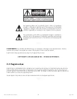
Page 8: ... COPYRIGHT 2014 ANALOGIA INC STUDIO ELECTRONICS 2 2 Registration Registering your BOOMSTAR synth establishes your ownership should there be a legal ownership dispute in the future which then secures access to Analogia Inc Tech Support and Warranty Service and if you so desire to product updates related information and promotional offers As always our RSS feed News page Facebook and Twitter outlets...

Page 9: ...REMOVAL PROCEDURE a Unplug female 3 prong IEC cable plug from 15 VDC power supply b Unplug female 3 prong IEC cable plug from AC outlet c Unplug Boomstar male 15 VDC power supply plug from female connector on the right side of back panel near bottom of synth marked Pin 1 Com IMPORTANT WARNING DO NOT POWER ON OR OFF THE BOOMSTAR BY ANY OTHER METHOD THAN THAT SPECIFIED ABOVE TO PREVENT DAMAGE TO UNI...

Page 10: ...red up its temperature regulated Oscillators will attain optimal temperature stabilization in 5 minutes at which point it is ready for tuning and accurate control of all parameters IMPORTANT WARNING DO NOT PATCH OUTPUTS TO OUTPUTS THE AUDIO OUT ON THE BACK PANEL MUST NOT BE PATCHED TO THE OSC OUT PATCH POINT ON THE FRONT PANEL ...

Page 11: ...Studio Electronics Boomstar Manual 7 Signal Flow Chart 3 SIGNAL FLOW CHART ...

Page 12: ...h Reset 4 PATCH RESET 3 1 Sawtooth Bass Patch Factory Reset We have talked to engineers and they advise starting and returning to this home base when puzzled or lost with this very basic patch to begin one s exploration of the Boomstar sound and structure ...

Page 13: ... S FRONT PANEL ADJUSTMENT HOLE SETTINGS TO INSURE UNIT IS NOT DAMAGED BE CERTAIN TO STRICTLY FOLLOW THIS REQUIREMENT AN IMPROPER TOOL AND OR IMPROPER USE OF SAID TOOL MAY RESULT IN SERIOUS DAMAGE TO SYNTHESIZER AND OR SERIOUS INJURY TO OPERATOR THE OPERATOR OF THIS SYNTHESIZER ASSUMES ALL RESPONSIBILITY AND LIABILITY ANALOGIA INC STUDIO ELECTRONICS OWNERS OFFICERS AND EMPLOYEES ASSUME NO RESPONSIB...

Page 14: ...tune adjust 5 1 1 9 9 Oscillator 2 octave adjust 5 1 1 10 10 Envelope Drive Set to full for Minim g back off for more Oberh m like sound 5 1 1 11 11 VCA Offset Uniform waveform adjust 5 1 1 12 12 VCA DC Balance De pops amplifier A detailed calibration video will be posted at http studioelectronics com support tutorials boomstar ...

Page 15: ...rol would include Modular synthesizers and step sequencers one volt per octave is the voltage specification 5 2 3 2 Gate Input External Gate Input a 5 voltage source is required to open the voltage controlled amplifier the alternative to MIDI note on and off 5 2 3 3 Voltage Controlled Filter Frequency Modulation Input Use an external control voltage to modulate the filter frequency modulation in t...

Page 16: ...s an external audio source and processes it through the Boomstar s filter and amplifier In order to hear the sound you will need to open the amplifier with either a gate or a MIDI note Patching the OSC OUT to the EXT IN pictured below will add additional depth harmonics and distortion ...

Page 17: ...becomes a clavi reedy nasal sound with odd harmonics only The RANGE switch selects the octave LO low frequency clicks and ticks below the audible range for humans clicks can make for very interesting rhythmic pulses and sequences 32 16 8 4 2 The LO setting of Oscillator 2 can be employed as a very flexible modulator These foot pitch numbers come from the lengths of organ pipes in the great cathedr...

Page 18: ...75 and 3003 self oscillating filters The SEM features a notch that sweeps from low pass to high pass as well as a band pass mode The SE80 is a multimode filter with dual frequency and resonance controls for the low pass and high pass response The Filter attenuates or cuts off the higher frequency components those which lie above the adjustable cutoff frequency and passes the lower frequency compon...

Page 19: ...time The attack time determines the initial segment of the envelope The frequency at which the contour begins is determined by the filter frequency setting while the peak which it reaches is determined by the filter frequency and Envelope 1 amount settings combined Incrementing the ATTACK knob value from 0 10 will result in the brightness of the sound increasing sharply at first and then more grad...

Page 20: ...r envelope The DECAY knob sets the decay time The decay time determines the duration of the drop in volume from the initial peak to the sustain level Shorter decay times will produce more percussive snappy sounds longer times open up and stretch out the sound Switching SINGLE TRIG single trigger on allows for the continuation of the decay cycle through a legato or multi note phrase Switching MULTI...

Page 21: ... analog synths to this day Use the switch to the right of the pot to select either 5 2 10 LFO Low Frequency Oscillator Atardy word about Modulation as a whole Modulation is the use of a control signal to create an often repetitive pattern of pitch level or harmonic and rhythmic content changes it infuses sound with movement and color The shape of the Boomstar s LFO is determined by the waveform th...

Page 22: ...ignal e g an amplifier is used to control the loudness of the sound over a period of time so as to emulate the natural amplitude shape and scope of a real instrument wait a minute an analog synthesizer is a real instrument The OVERDRIVE switch engages the overdrive circuit in the top position it is on The VOLUME knob sets the master volume of the synthesizer 5 2 12 Master Tune Sets the master tuni...

Page 23: ...eshold 5 2 17 2 Sets the mix level of Oscillator 2 Default setting should be 75 of full if a clean sound is in order see previous Otherwise employ at full strength 5 2 17 3 Sets the mix or heterodyne of OSC 1 and OSC 2 and outputs the sum and difference of the frequencies present in each waveform tech y Expect to hear tones thick in harmonics and suitable for producing bell like warm metallic soun...

Page 24: ...serial numbers 100 343 are equipped with Verson 2 OS 5 3 1 3 Excludes Boomstars manufactured to run only on 100 VAC for the Japanese market FOLLOWING THE BOOMSTAR POWER ADAPTER CONNECTION PROCEDURE IS ESSENTIAL TO THE PROPER FUNCTIONING OF YOUR UNIT DON T DAMAGE YOUR BOOMSTAR AND VOID YOUR WARRANTY BY HOT SWAPPING THE POWER TO THIS SYNTHESIZER The proper power connection disconnection procedure an...

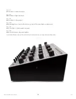
Page 25: ...EMPLOYEES ASSUME NO RESPONSIBILITY OR LIABILITY FOR PERSONAL AND PROPERTY DAMAGE INCURRED DUE TO ACCIDENT CARELESS HANDLING ABUSE OR MISUSE IMPROPER CONNECTION INSTALLATION OR IMPROPER ELECTRICAL CONTACT OR GROUNDING OWNERSHIP AND OR USE OF BOOMSTAR SYNTHESIZER CONSTITUTES AN AGREEMENT WITH THESE TERMS 5 4 Side Panel 5 4 1 Holes allow for rackmount bracket kit to be attached Contact us at studioel...

Page 26: ...w all installation instructions Failure to follow instructions could void your FCC authorization to use this product in the USA NOTE This product has been tested and found to comply with the requirements listed in FCC Regulations Part 15 for Class B digital devices Compliance with these requirements provides a reasonable level of assurance that your use of this product in a residential environment...

Page 27: ... 6 3 Canada NOTICE This class B digital apparatus meets all the requirements of the Canadian Interference Causing Equipment Regulation 6 4 Europe AVIS Cet appareil numérique de la classe B respecte toutes les exigences du Règlement sur le matériel brouilleur du Canada This product complies with the requirements for European Directive 89 336 EEC This product complies with the requirements of Europe...

Page 28: ...IN Input LFO Low Frequency Oscillator LO Low MOD Modulation MULTI Multiple OSC Oscillator OUT Output PW Pulse Width SYNC Synchronisation TRIG Trigger VCA Voltage Controlled Amplifier VCF Voltage Controlled Filter VCO Voltage Controlled Oscillator WAVE Waveform Other Non Screened Terminology 0 all the way counter clockwise 10 all the way clockwise ...

Page 29: ...adder based designs That s normal The SEM filter is OTA based and is 12db octave It is also a multi mode filter highpass lowpass bandpass notch and various mixes in between It s ballsy crisp and clear and gain actually increases with resonance but the filter will not go all the way to oscillation at high settings due to parts tolerances some might but not all The CS80 filter pair is bright and buz...

Page 30: ... or Shi Chi written more than a century later round about midnight on one fine evening day in 100 B C one can discover how the broom star bristly tail yo in 240 B C was seen at the north direction and then at the west direction during the summer the Empress Dowager died Variant readings interpret its appearance in the east and movement north ish THE POINT BEING the broom star s albedo or reflectio...

Page 31: ...Studio Electronics Boomstar Manual 27 Back Panel 10 BACK PANEL ...

Page 32: ...18 5 2 11 Set Feedback to 0 see p 19 5 2 17 5 Unwanted Noise Don t be tasty with feedback its lowest settings can add noticeable hash see p 19 5 2 17 5 Unwanted Sustaining Sound Turn off drone see pp 16 5 2 8 Out of Tune Set master tuning to 440 Hz see p 18 5 2 12 Or one could experiment with 432 Hz as was done here with our Boomstar SEM http www youtube com watch v aQza J2kmUA hd 1 Of esoteric in...

Page 33: ...Studio Electronics Boomstar Manual 29 Blank Patch Sheet 1 12 Blank Patch Sheet 1 5089 4075 3003 SEM Boomstar Patch Sheets Rev 1 2 Analogia Inc 2014 ...

Page 34: ...30 Studio Electronics Boomstar Quick Start Manual Blank Patch Sheet 2 13 Blank Patch Sheet 2 SE80 700 Boomstar Patch Sheets Rev 1 2 Analogia Inc 2014 ...

Page 35: ......

Reviews: