Stuart Turner 41712 Installation, Operation & Maintenance Instructions Manual Download Page 20

- 20 -

Horizontal Step 2:

The vessel assembly should then be positioned and checked to ensure there is  


sufficient space to install the upstream line-in kit between the stopcock and  


pressure vessel inlet.  Refer to the chart below as a guide.

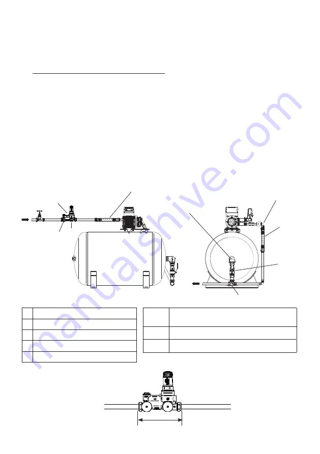
Monobloc 22/28mm Upstream line-in kit

The Monobloc upstream line-in kit includes:

1 - Monobloc unit

2 - Pressure gauge (upstream)

3 - Pressure gauge (downstream)

4 - Vessel Connector (see step 1)

5 - Isolation Valve (see step 1)

NOTE: the Monobloc can be installed either horizontally or vertically but not upside

down. There are pressure gauge ports on both sides of the Monobloc to allow the

pressure gauges to be visable in any orientation. Follow the directional flow arrows

on the Monobloc to ensure correct installation.

NOTE: It is good practice to install a drain port between the isolation valve and the 

vessel.

1 Monobloc unit

2 Pressure gauge (upstream)
3 Pressure gauge (downstream)
4 Mainsboost vessel connector
5 Lever isolating valve

Fig. 24a

Pipe 

Size

Minimum pipe length required to install 

the Monobloc upstream in line kit (mm) (A)

22 mm 203 mm

28 mm 203 mm

A

Inlet

Outlet

1

2

Flexible

hose

4

5

Flexible 

hose

3

Fig. 23a

Push fit elbow 

(not supplied)

T-piece (not supplied)

Summary of Contents for 41712

Page 1: ...ainsboost Charger Pump MJ3 Vessel Mounted Previously named Mainsboost Plus both vertical horizontal variants Mainsboost Charger Installation Operation Maintenance Instructions Please leave this instru...

Page 2: ...consistent and reliable water services Installation parameters must not exceed the values given in the technical specifications STORAGE If this product is not to be installed immediately on receipt e...

Page 3: ...ead closed valve 43 metres z The motor casing can become very hot under normal operating conditions Care must be taken to ensure it cannot be touched during operation z The electrical installation mus...

Page 4: ...g and securing details are carefully noted to ensure re assembly to the same factory pattern is always maintained z If the supply cord is to be changed or is damaged it must be replaced with a special...

Page 5: ...set 6 Pump mounting bolt assembly 1 set Your product may vary slightly from the illustrations above Mainsboost Charger MJ3 Vertical Mainsboost Monobloc 22 28mm ULK IMPORTANT Your Mainsboost Charger M...

Page 6: ...y 1 set 7 Double check valve 1 6 Pump mounting bolt assy 1 set 8 BSP Pressure gauge 1 Your product may vary slightly from the illustrations above Mainsboost Charger MJ3 Vertical 35 42 54mm ULK IMPORTA...

Page 7: ...t 1 Package 2 1 Mainsboost vessel 1 2 BSP Pressure gauge 2 2 Mounting cradle 2 3 Lever isolating ball valve 1 Package 3 1 Pump 1 4 Mainsboost vessel connector fitting 1 2 Sealing washers 2 5 22 28mm c...

Page 8: ...lating ball valve 1 2 Mounting cradle 2 3 Mainsboost vessel connector fitting 1 Package 3 1 Pump 1 4 6 bar pressure regulating valve 1 2 Sealing washers 2 5 x BSP Brass bush 1 3 Manifold assembly 1 6...

Page 9: ...pressurised to an optimum setting When water is drawn off by downstream services the water from the mains is supplemented by the water from the Mainsboost Charger MJ3 unit to provide a balanced supply...

Page 10: ...outlet branches of pump Flexible hoses supplied must be used 2 15 Flux Solder joints must be completed and flux residues removed prior to pump installation flux damage will void any warranty 2 16 Pipe...

Page 11: ...ely event of a water leak any spillage is contained or routed to avoid electrics or areas sensitive to water damage 3 16 Static inlet pressure Ensure the static inlet head at the pump does not exceed...

Page 12: ...k and the Mainsboost vessel 4 12 System Designation It is important to understand what upstream and downstream refers to before starting the installation Upstream The term Upstream refers to the syste...

Page 13: ...for example utility kitchen upstairs cupboard or loft providing adequate provisions are taken for the weight frost protection etc see Fig 7 Where height restrictions exist the MJ3 HM pump can be supp...

Page 14: ...parallel to ensure sufficient water is on tap to meet the much higher demand Fig 9 shows all vessels being located in the same place 5 15 Water softener NOTE If high pressure is also required to the d...

Page 15: ...base and push into vessel connector Pipe length MB 100SV 210 mm MB 200SV 270 mm MB 300SV 270 mm MB 130SV 210 mm MB 250SV 270 mm MB 450SV 340 mm Then re erect the cylinder e Fit the isolating valve pro...

Page 16: ...additional space must be allocated for this Do not fit smaller pipework than the upstream line in kit accepts as this will impair performance h Fix the Mainsboost vessel securely to the floor using a...

Page 17: ...of the Monobloc to allow the pressure gauges to be visable in any orientation Follow the directional flow arrows on the Monobloc to ensure correct installation Upstream line in kit 35 42 54mm The upst...

Page 18: ...sure the mounting cradles are as far apart as possible but within the weld seams Fig 18b WARNING depending on cylinder size this may require two people to complete safely Remove the skirt by splitting...

Page 19: ...ied hoses Fig 22 Inlet Outlet Manifold assembly Bypass valve and integral NRV Fig 22 Sealing washers Pump mounting bracket assembly Fig 19 3 8 bolt Mounting bracket Mounting pump onto the vessel Fig 2...

Page 20: ...tally or vertically but not upside down There are pressure gauge ports on both sides of the Monobloc to allow the pressure gauges to be visable in any orientation Follow the directional flow arrows on...

Page 21: ...operation NOTE It is good practice to install a drain port between the isolation valve and the vessel 1 Inline strainer 2 Pressure gauge upstream 3 Double check valve 4 Pressure reducing valve 5 Pres...

Page 22: ...und Attenuation Covers Vertical Horizontal An attenuation cover A is available as an option should the unit need to be installed in a particularly noise sensitive area Vertical Fig 25 A Horizontal Fig...

Page 23: ...anently connected to the fixed wiring of the mains supply using the factory fitted supply cord via a dedicated double pole switched fused spur off the ring main 7 17 Wiring of connection unit WARNING...

Page 24: ...to the same factory pattern is always maintained 7 21 If the supply cord is to be changed or damaged it must be replaced by a special cord available from Stuart Turner or one of its approved repairers...

Page 25: ...the vessel is empty contains no water 8 13 Check mains static pressure z Now close outlets and check pressure gauge after Y strainer for static mains pressure and note it This should be done at peak t...

Page 26: ...own arrows to change the selected parameter s to the desired value z After changing the required parameter s press the set button twice in quick succession to lock the new value into the controller me...

Page 27: ...illing of the system z Close Mainsboost vessel isolation valve z Allow the pump to continue running until air has been completely purged from the system all outlets will have to be opened and closed z...

Page 28: ...Induction auto reset thermal trip Duty rating Continuous S1 Electrical Power supply Vac Ph Hz 230 V a c 1 50 Hz Power consumption P1 398 Watts Current full load 1 8 Amps Fuse rating 3 Amps Power cable...

Page 29: ...1280 mm 1300 mm 535 mm 548 mm MB 250SV MJ3 VM 1455 mm 1475 mm 535 mm 548mm MB 300SV MJ3 VM 1740 mm 1760 mm 535 mm 548 mm MB 450SV MJ3 VM 1775 mm 1795 mm 660 mm 660 mm Model Description Dim H1 Dim H2 D...

Page 30: ...larm fault codes All alarms automatically reset except Prt and PF1 Displayed message Fault description Action A Hnt high temp cut out Pump head overheating head temperature has exceeded the set Hnt va...

Page 31: ...vered by this warranty Damage arising from incorrect installation improper use unauthorised repair normal wear and tear and defects which have a negligible effect on the value or operation of the unit...

Page 32: ...0 3 3 BS EN 61000 4 2 BS EN 61000 4 3 BS EN 61000 4 4 BS EN 61000 4 5 BS EN 61000 4 6 BS EN 61000 4 11 EMF Directive 1999 519 EC BS EN 62233 RoHs Directive 2011 65 EU WEEE Directive 2012 19 EU IT IS H...

Reviews: