Stryker Hansson Pin System Manual Download Page 8

8

Step 3 – Stabilization Guide 
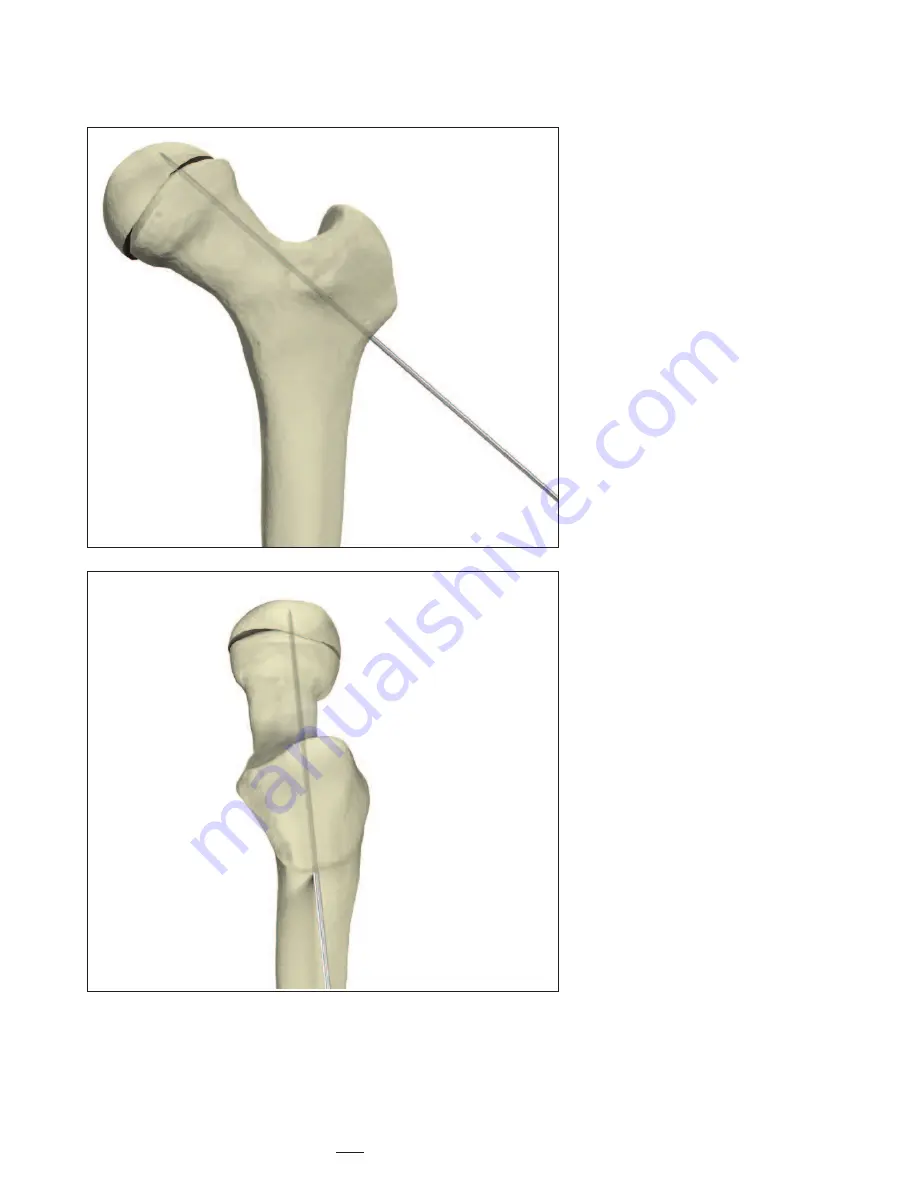
Wire Insertion

When treating unstable (acute) 
slips 
a Guide Wire may be used.
Using biplanar floroscopy, it is inserted
percutaneously in the trochanteric
region into the femoral neck and 
head for intraoperative stabilization.
(Fig. 5).

Fig. 5

Operative Technique

Summary of Contents for Hansson Pin System

Page 1: ...5 Slipped Capital Femoral Epiphysis Operative Technique Hansson Pin System Pediatrics ...

Page 2: ...Stabilization Guide Wire Insertion 8 Determining the Incision and Insertion Points 9 Skin Incision and Guide Wire Insertion 10 Drilling and Measurement 11 Instrument to Pin Assembly 12 Insertion of the Hansson Pin 13 and Activation of the Hook Instrument Removal 14 Postoperative Regime 15 Pin Removal 16 Ordering Information Implants 17 Instruments 18 References 19 ...

Page 3: ...s of successful clinical studies have been carried out to enhance the Hansson Pin System to its current form This work is summarized in 6 theses and more than 70 published articles Rationale The methodology involves a cylindrical pin inserted in a drill hole which attaches to the femoral head via a hook providing strong stable fixation through a simple and precise procedure The drill hole and pin ...

Page 4: ... of the device or to failure of the device itself Patients having inadequate tissue coverage over the operative site Implant utilization that would interfere with anatomical structures or physiological performance Any mental or neuromuscular disorder which would create an unacceptable risk of fixation failure or complications in postoperative care Other medical or surgical conditions which would p...

Page 5: ...ng the femoral head Loosening of the implant is potentially reduced because of resorption and growth of the femoral neck under normal conditions 1 Reducing the risk of unequal bone length The continued growth of the femoral neck in cases with Slipped Capital Femoral Epiphysis is an indication of undisturbed intra and postoperative vascularization as the nutrition for the proliferating cells of the...

Page 6: ...ior posterior and the lateral medial views This is necessary to obtain a true lateral view of the femoral neck and head Fig 2 The purpose of this view is to avoid the penetration of the end of the pin through the surface of the femoral head Furthermore again for avoiding pin penetration the surface of the femoral head must be seen continuously when moving the C arm from the horizontal position to ...

Page 7: ... The remodelling is therefore ossified and reduction is not possible The stable slip is pinned with the intention of preventing further slippage as well as preventing the possibility of acute on chronic traumatic changes which could be devastating for the vascularization of the femoral head The surgical treatment of a stable slip can therefore be planned in advance but must be considered urgent Fi...

Page 8: ...ion When treating unstable acute slips a Guide Wire may be used Using biplanar floroscopy it is inserted percutaneously in the trochanteric region into the femoral neck and head for intraoperative stabilization Fig 5 Fig 5 Operative Technique ...

Page 9: ...ect position in the central part of the femoral neck and head Fig 7 Mark the position of the Guide Wire on the anterior surface of the thigh Lateral Medial View Now position the Guide Wire over the skin on the lateral aspect of the thigh Verify by lateral medial fluoroscopy that the Guide Wire has been positioned to enter posteriorly towards the central part of the femoral head Fig 8 Mark the posi...

Page 10: ...e center of the femoral head According to the severity of the slip the guide wire will be in an oblique position in the femoral neck Use frequent biplanar fluoroscopic control to verify the alignment of the Guide Wire in both the anterior posterior and lateral medial plane This is to ensure that the centre of the femoral head will be reached If the direction of the Guide Wire appears to deviate fr...

Page 11: ...subchondral bone Leave the Drill Sleeve in place Read the measurement shown on the drill at the level of the lateral aspect of the Drill Sleeve See zoom of Fig 12 Choose a Hansson Pin which is about 15 to 20mm more than the measurement shown This is to allow the femoral neck to continue its growth along the pin and to ease pin removal once the physis has closed and growth has completed According t...

Page 12: ...oducer through the Outer Introducer and screw it into the Hansson Pin Fig 14 There are unequal tabs on the Outer Introducer which correspond with slots in the pin the tabs and slots should securely mate when the Introducer Assembly is screwed onto the Hansson Pin The handles of the Inner and Outer Introducers need not be aligned Fig 13 Fig 14 Hansson Pin Outer Introducer Inner Introducer ...

Page 13: ...nment with the femoral shaft Fig 16 Thus the hook will be extruded in the superior direction as demonstrated in figure 17 Insert the tip of the Introducer Handle through the hole in the Inner Introducer Maintain both the Outer and Inner Introducers in position Turn the Introducer Handle clockwise whilst gently pushing medially on the introducer assembly Continue turning the Introducer Handle to co...

Page 14: ...e Technique Step 9 Instrument Removal Maintain the Outer Introducer in position Unscrew and then remove the Introducer Handle followed by the Inner Introducer and the Outer Introducer Fig 18 Close the wound Fig 18 ...

Page 15: ...n the implants which may lead to fixation or implant failure and accompanying clinical problems Surgeons should also instruct parents to report any unusual changes of the operative site to his her physician The physician should closely monitor the patient if a change at the site has been detected Bilateral Slips Periodic X Ray images should be taken of both hips to facilitate early detection of co...

Page 16: ...Extractor in place Insert the threaded tip of the Extractor Handle into the Outer Extractor and turn it clockwise to engage the threaded part of the Inner Extractor Do not rotate the Outer Extractor See step 1 in figure 20 Continue to turn the Extractor Handle until a mechanical stop is felt This completely withdraws the hook into the outer pin Check under image intensification that the hook is fu...

Page 17: ... 694080S 394085S 85mm 694085S 394090S 90mm 694090S 394095S 95mm 694095S 394100S 100mm 694100S 394105S 105mm 694105S 394110S 110mm 694110S 394115S 115mm 694115S 394120S 120mm 694120S 394125S 125mm 694125S 394130S 130mm 694130S 394135 135mm 694135 394140 140mm 694140 HANSSON PINS Special Order Note Sterile Only Special Order Non Sterile ...

Page 18: ...04511 Guide wire Bush 704515 Outer Introducer 704516 Inner Introducer 704517 Introducer Handle 704527 Extractor Handle 704528 Outer Extractor 704529 Inner Extractor 704505S Threaded Guide wire Ø 2 4mm x 300mm Single Use Sterile Packed 901704 Sterilisation Tray for Instruments Lid and Insert Optional Instrument 702448 Drill Bit Ø 1 4mm x 150mm single use ...

Page 19: ...emoral Epiphysis A 30 year follow up of 59 hips The Journal of Bone and Joint Surgery Br 1998 80 B 70 7 Hansson G Billing B Högstedt B Jerre R Wallin J 7 Prophylactic Pinning of the Contralateral Hip in Slipped Capital Femoral Epiphysis Evaluation of Long Term Outcome for the Contralateral Hip with Use of Decision Analysis Journal of Bone and Joint Surgery Inc 2002 W Randall Schultz MD MS James N ...

Page 20: ...ich products and techniques to use with their patients Products may not be available in all markets Product availability is subject to the regulatory or medical practices that govern individual markets Please contact your Stryker representative if you have questions about the availability of Stryker products in your area Stryker Corporation or its subsidiary owns the registered trademark Stryker S...

Reviews: