4
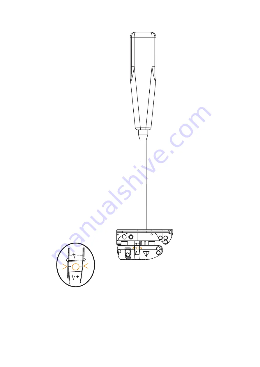
1 Adjust to Neutral Position
1.1 Insert the screwdriver into the screwdriver
interface.
1.2 Rotate the screwdriver until the cutting
guide is set to the 0 marking.
Instructions
Page 1: ...1 Navigated MIS Jig A REF 6003 200 010 Navigated MIS Jig B REF 6003 200 020 Tracker Adapter REF 6003 200 030 TD6003200700 2021 04 07 Rev AA Instructions For Use Patent ...
Page 2: ...dent nurse professional caregiver edu cated in computer assisted surgery and thoroughly familiar with the instructions for use and with the operation of this product To request an additional in service instruc tion contact Stryker NOTE In the following text the Navigated MIS Jig A Navigated MIS Jig B is referred to as cutting guide NOTE The following conventions are used in this document The signa...
Page 3: ...ort any serious product related incident to both the manufacturer and the national competent authority where the user and or patient is established User Patient Safety WARNING Read and understand this information File it in your maintenance records Familiarization with the Stryker naviga tion system prior to its use is important Refer to the instructions for use sup plied with the navigation syste...
Page 4: ...4 1 Adjust to Neutral Position 1 1 Insert the screwdriver into the screwdriver interface 1 2 Rotate the screwdriver until the cutting guide is set to the 0 marking Instructions ...
Page 5: ...pter into the cutting guide 2 2 For tracker camera alignment choose between the two adjustment angles of the Tracker Adapter on the cutting guide 2 3 Release the release button and rotate the Tracker Adapter until the release button snaps in the required position Verify that the Tracker Adapter is correctly engaged in the cutting guide Cutting Guide ...
Page 6: ...at the Tracker Adapter is engaged and secure Green marking is visible Gap between Tracker Adapter and Cutting Guide Green marking not visible CORRECT engaging Tracker Adapter is flat on the Cutting Guide INCORRECT engaging ...
Page 7: ...7 Instructions 3 Mount Tracker on Tracker Adapter 3 1 Mount the tracker onto the interface of the Tracker Adapter Note The tracker in the below image is shown in principle Cross pin must engage ...
Page 8: ... settings for preliminary fixation 4 2 For preliminary fixation insert a pin into the swivel of the adjustment block as depicted in the detail above 5 Varus Valgus and Flexion Extension Alignment 5 1 Align the cutting guide according to the varus valgus and flexion extension setting as displayed on the navigation screen Hole for pin insertion Adjustment Block ...
Page 9: ...te Adjustment Block 6 1 Insert two pins into the adjustment block for fixation as depicted in the detail above Ensure that the adjustment block is stable and can not move relative to the bone Holes 4 total for pin insertion ...
Page 10: ...The scale is not calibrated Refer to the navigation screen for adjustment 8 Final Fixation of Cutting Block 8 1 Insert two pins into the cutting block for fixation as depicted in the detail above 8 2 Remove the Tracker Adapter by pressing the release button Cutting Block Holes 4 total for pin insertion ...
Page 11: ...11 Instructions 9 Bone Cut 9 1 Insert the blade for cut 9 2 Proceed to cut ...
Page 12: ...aning Disinfection Sterilization and Inspection Instructions Cleaning group IV Refer to the Guide for Cleaning Disinfection and Steam Based Sterilization TD6000005750 for cleaning safety and caution notes cleaning equipment and de tailed cleaning and inspection instructions Disposal Products that have been in contact with material of human origin may be infectious Dispose of with the necessary pre...
Page 13: ... REF 6003 100 110 Headless pins 3 175 mm 1 8 inch diameter e g REF 6003 003 090 REF 7650 1038 Saw blades 1 27 mm 0 05 inch thickness e g REF 2108 189 REF 6625 127 105 Technical Specifications Model Navigated MIS Jig A REF 6003 200 010 Navigated MIS Jig B REF 6003 200 020 Tracker Adapter REF 6003 200 030 Size 40 5 x 43 1 x 11 mm 1 57 x 1 69 x 0 43 inch Tracker Adapter 54 5 x 25 x 31 mm 2 14 x 0 9 x...
Page 14: ...t damaged Return Tracker Adapter and cutting guide to service The pin can not be inserted jams The pin is bent dam aged or not properly sized Replace if damaged or not suitable The saw blade can not be inserted has too much play or jams The saw blade can not be inserted has too much play or jams The blade is bent damaged or not prop erly sized slot is worn Replace if damaged or not suitable Resect...
Page 15: ...turer s catalog number so that the medical device can be identified NON STERILE Non sterile Indicates a medical device that has not been subject ed to a sterilization process Consult instructions for use Indicates the need for the use to consult the instructions for use Humidity limitation Indicates the range of humidity to which the medical device can be safely exposed Temperature limit Indicates...
Page 16: ...or have applied for the following trademarks or service marks Leibinger Stryker All other trademarks are trademarks of their respective owners or holders Copyright 2005 2021 Stryker Stryker Leibinger GmbH Co KG Bötzinger Straße 41 79111 Freiburg Germany t 49 761 4512 0 Germany t 1 269 323 7700 USA REF 6003 200 010 REF 6003 200 020 REF 6003 200 030 ...