background image

P

9 f 11

CLEANING: 

WARNING:


UNPLUG FROM ELECTRICAL SUPPLY BEFORE CLEANING. 

1.  Use a soft, damp cloth (water only) for cleaning, then wipe with dry cloth. 
2.  Don’t not use cleaners that harm paints or plastics; i.e., bleach or ammonia.  
3.  Do not bend blades 

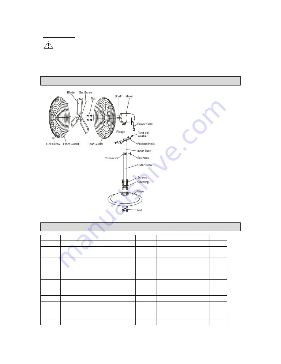
Parts Diagram 


Parts List 

Part# Description  Qty. 

Part# Description Qty. 

SCREWS 6 

12 

POWER CORD 

COUPLING (ATTACHED 

TO OUTER TUBE) 

13 

FLANGE (ATTACHED 

TO MOTOR) 

OUTER TUBE 

14 

MOTOR 1 

BASE 1 

15 

SHAFT 1 

NUT (TO ATTACH BASE 

TO OUTER TUBE) 

16 

REAR GUARD 

SET KNOB (TO 

CONNECTOR) 

17 

NUT (TO ATTACH 
REAR GUARD TO 

MOTOR) 

INNER TUBE 

18 

BLADE 1 

POSITION KNOB 

19 

SET SCREW 

PIVOT BOLT 

20 

FRONT GUARD 

10 

WASHER 1 

21 

GRILL SCREW 

11 

NUT 1 


Summary of Contents for 49939

Page 1: ...Owner s Manual WARNING Read carefully and understand all ASSEMBLY AND OPERATION INSTRUCTIONS before operating Failure to follow the safety rules and other basic safety precautions may result in serious personal injury Item 49939 ...

Page 2: ... This fan is designed for certain applications only The distributor cannot be responsible for issues arising from modification or use of this product in an application for which it was not designed We strongly recommend that this product not be modified and or used for any application other than that for which it was designed If you have questions about a particular modification or application DO ...

Page 3: ...y Rules Error Bookmark not defined Important Safety Considerations 5 Specific Operation Warnings 7 Safety Labels 7 Assembly 7 Before Each Use 8 Operating Instructions 8 After Each Use 8 Maintenance 8 Parts Diagram 9 Parts List 9 Troubleshooting 10 Replacement Parts 10 Limited Warranty 10 ...

Page 4: ...serious injury The warnings cautions and instructions in this manual cannot cover all possible conditions or situations that could occur Exercise common sense and caution when using this tool Always be aware of the environment and ensure that the tool is used in a safe and responsible manner DO NOT allow persons to operate or assemble this product until they have read this manual and have develope...

Page 5: ... shock do not expose fan to water or rain To reduce the risk of fire or electrical shock do not use this fan with any solid state speed control device Automatically operated device to reduce risk of injury disconnect from power supply before servicing If the power supply cord is damaged contact your local service centre or a qualified electrician to install an appropriate replacement cord to preve...

Page 6: ...e sure fan is placed on a secure level surface Does not use fan in windows Rain and moisture may create electrical hazard Close supervision is necessary when this fan is used near children the elderly and pets Do not place the fan near an open flame cooking or heating appliance or hot surface This fan should NOT be operated outside o CAUTION Do not alter fan s assembly WARNING Be sure that both fr...

Page 7: ...Keep guards in place and in working order Never operate the fan without the guards in place Do not leave the tool running unattended Inspect the fan for damage or excessive wear before each use If you find damage do not use the fan Specific Operation Warnings Be sure that both front and rear grille screws are completely tightened before operation Safety Labels Assembly COLUMN BASE ASSEMBLY INSTRUC...

Page 8: ...ooling TO ADJUST AIRFLOW UPWARD OR DOWNWARD o Loosen the POSITION KNOB first then loosen the NUT of the PIVOT BOLT Tilt fan head to the desired angle then firmly tighten the POSITION KNOB then tighten the NUT of the PIVOT BOLT SPEED CONTROL Set switch to LOW or HIGH speeds or OFF respectively NOTE It is normal for the motor to feel warm to touch after continuous operation This fan features a therm...

Page 9: ...s Diagram Parts List Part Description Qty Part Description Qty 1 SCREWS 6 12 POWER CORD 1 2 COUPLING ATTACHED TO OUTER TUBE 1 13 FLANGE ATTACHED TO MOTOR 1 3 OUTER TUBE 1 14 MOTOR 1 4 BASE 1 15 SHAFT 1 5 NUT TO ATTACH BASE TO OUTER TUBE 6 16 REAR GUARD 1 6 SET KNOB TO CONNECTOR 1 17 NUT TO ATTACH REAR GUARD TO MOTOR 4 7 INNER TUBE 1 18 BLADE 1 8 POSITION KNOB 1 19 SET SCREW 1 9 PIVOT BOLT 1 20 FRO...

Page 10: ... the warranty period Strongway will repair or replace the unit at a predetermined charge This warranty does not apply to damage from shipping mishandling accident misuse alternation improper power voltage improper installation exposure to extremes of heat and humidity industrial use outdoor use failure due to hardware not supplied by Ironton If defective within the limitation of this warranty plea...

Page 11: ...Page 11 of 11 Distributed by Northern Tool and Equipment Company Inc Burnsville Minnesota 55306 NorthernTool com Made in China ...

Reviews: