background image

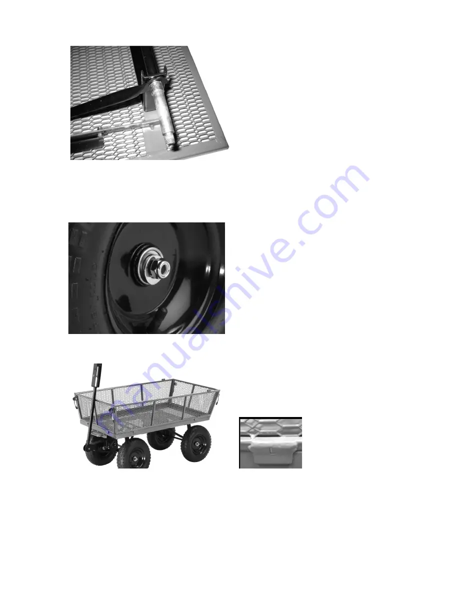
7. Attach the wheels to the cart by first placing the wheel spacers (4) onto the front and rear axles.     


8. Place the wheels onto each axle (valve stems facing out) using the M12 flat washers (4) and M12 

lock nuts (4).    Tighten all nuts securely.     

Turn cart upright. 


9. Attach the mesh panels to the side of the bed frame.    Each panel has a letter stamped on it (L, R, 

F, B) that corresponds to the same letters stamped on the bed frame itself. 


Page    of 12 

Summary of Contents for 46530

Page 1: ...ER S MANUAL WARNING Read carefully and understand all ASSEMBLY AND OPERATION INSTRUCTIONS before operating Failure to follow the safety rules and other basic safety precautions may result in serious personal injury Item 46530 ...

Page 2: ...apacity Overall maximum 1 200 lbs load capacity Maximum 500 lbs dumping load capacity when cart is loaded Tires 13 inch Pneumatic Tires Do not inflate the tires to more than 30 PSI Construction Steel frame with poly bed tray Dimensions 44 x 24 x 24 75 GENERAL SAFETY RULES WARNING Read and understand all instructions Failure to follow all instructions listed below may result in serious injury CAUTI...

Page 3: ...tended for highway use Do not exceed 5 mph Do not use this cart for transporting passengers Do not allow children to use this cart without supervision This cart is not a toy Do not inflate the tires to more than 30 PSI Do not use the cart on surfaces or for transporting objects that can cause damage to the pneumatic tires Always check of damaged or worn out parts before using the cart Broken parts...

Page 4: ...art Description Qty A Bed Frame 1 B Poly Liner Cover 1 C Front Panel 1 D Left Panel 1 E Right Panel 1 F Back Panel 1 G Front Axle Assembly 1 H Rear Axle Assembly 1 I Front Struts 2 J Rear Struts 2 K Wheels 4 L Handle 1 M Coupling 1 Page of 12 4 ...

Page 5: ...axle assembly under the frame to prop it up for easier access Attach the front axle assembly to the bed frame using M8x20 carriage bolts 4 M8 flat washers 4 and M8 lock nuts 4 The bolts should go through the frame first and then the front axle assembly 3 Attach the front struts 2 to the bed frame using M8x20 carriage bolts 2 M8 flat washers 2 and M8 lock nuts 2 Slide the M8x20 carriage bolts throu...

Page 6: ...dware securely 5 Attach the rear axle assembly to the bed frame using M8x20 carriage bolts 2 M8 flat washers 2 and M8 lock nuts 2 Hand tighten 6 Slide the rear struts onto the rear axle assembly and attach the angled part of the strut to the bed frame using M8x20 carriage bolts 2 M8 flat washers 2 and M8 lock nuts 2 Tighten all hardware securely Page of 12 6 ...

Page 7: ...els onto each axle valve stems facing out using the M12 flat washers 4 and M12 lock nuts 4 Tighten all nuts securely Turn cart upright 9 Attach the mesh panels to the side of the bed frame Each panel has a letter stamped on it L R F B that corresponds to the same letters stamped on the bed frame itself Page of 12 7 ...

Page 8: ...f the side panels Lock the tray in place by sliding cotter pins through the tabs The plastic tray can also be used as a cover work surface Lock the tray by sliding the cotter pins through the tabs 11 Attach handle to the yoke using M8x60 bolt 1 M8 flat washer 1 and M8 lock nut 1 Tighten securely Page of 12 8 ...

Page 9: ...SING THE DUMPING FEATURE To use the dumping feature pull the dumping release handle forward in order to release the tray from the locking mechanism Lift the release handle in order to rotate the tray upward into the dumping position WARNING To reduce risk of injury when dumping ensure worksite is clear and free of hazards and bystanders RETURNING THE TRAY TO THE LOWERED POSITION Return the tray ba...

Page 10: ...ommended that the general condition of any cart be examined before it is used Keep your cart in good repair by adopting a program of conscientious repair and maintenance Have necessary repairs made by qualified service personnel Page of 12 10 ...

Page 11: ... 1 D Left Panel 1 E Right Panel 1 F Back Panel 1 G Front Axle Assembly 1 H Rear Axle Assembly 1 I Front Struts 2 J Rear Struts 2 K Wheels 4 L Handle 1 M Coupling 1 N Hardware Kit 1 For replacement parts and technical questions please call 1 800 222 5381 Page of 12 11 ...

Page 12: ...WARRANTY 1 Year Limited Warranty Distributed by Northern Tool Equipment Co Inc Burnsville Minnesota 55306 NorthernTool com Made in China Page of 12 12 ...

Reviews: