


Bulb Goes Out During Operation
(continued)
2. Overheated thermal switch in xenon power supply. Check for unobstructed air flow through power supply;
loose DC connection(s).
3. Phase loss or unstable AC input to xenon power supply. See power supply manual (Phase Loss Detection
and Brown-Out Protection).
4. Faulty automation contact. If lamp operates normally in MANUAL mode, check automation controller.
5. Faulty xenon bulb. Check for darkened or damaged electrodes, discolored envelope, instability in operating
current or voltage. Replace if defective.
Excessive Light Flicker
1. Defective xenon bulb. Check for cracked and/or sagging electrode.
2. Arc stabilization magnet missing or reversed. Replace or correct; painted end of magnet should point
toward operator’s side access door.
3. Projector shutter mis-timed. See projector manual.
4. Excessive ripple in DC current. See power supply manual.
Reduced Light Output
1. Normal bulb aging. Increase current. Do not exceed the maximum current rating specified by the xenon
bulb manufacturer.
2. Defective bulb. Check for premature darkening of envelope; subnormal arc voltage.
3. Bulb defocused or misaligned. Repeat bulb alignment procedure.
4. Reflector coating peeled or discolored. Replace reflector.
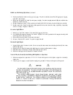
Noise in Theatre Sound System During Bulb Ignition or Operation
1. Defective suppression capacitor(s) C1, C2, C3. Check with capacitor tester; replace capacitor or assembly
if defective.
2. Console, power supply, or sound system improperly grounded. Connect to adequate earth ground.
NOTICE
The Strong DC Pulse Igniter stores energy in its capacitors
after the console
has been de-energized. To prevent shock, this energy can be discharged by
placing the blade of an insulated-handle screwdriver across the metal end
caps of the spark gap.
The Strong switching-type Xenon Power Supply employs solid state
circuitry requiring sophisticated diagnostic equipment not generally available
to field service personnel. If an ignition problem in the TROUBLE CHART
section is traced to this unit, contact an authorized Strong International
Dealer for further information.
X90/029
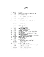
Summary of Contents for X-90
Page 2: ......
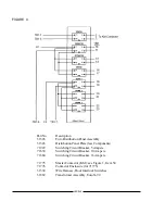
Page 21: ...X 90 LAMPHOUSE SCHEMATIC Analog Controls X90 019 ...
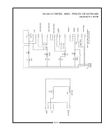
Page 23: ...ANALOG CONTROL PANEL PRINTED CIRCUIT BOARD Assembly No 23239 X90 021 ...
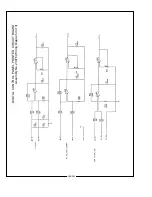
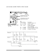
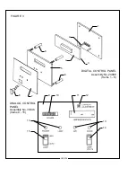
Page 24: ...X90 022 DIGITAL CONTROL PANEL PRINTED CIRCUIT BOARD Assembly No 23976 Wiring Diagram 1 of 3 ...
Page 25: ...X90 023 DIGITAL CONTROL PANEL PRINTED CIRCUIT BOARD Assembly No 23976 Wiring Diagram 2 of 3 ...
Page 26: ...X90 024 DIGITAL CONTROL PANEL PRINTED CIRCUIT BOARD Assembly No 23976 Wiring Diagram 3 of 3 ...
Page 43: ......
Page 44: ......


