S-CB
+
Boiler Range Manual
18
6.3 Flow and return connections
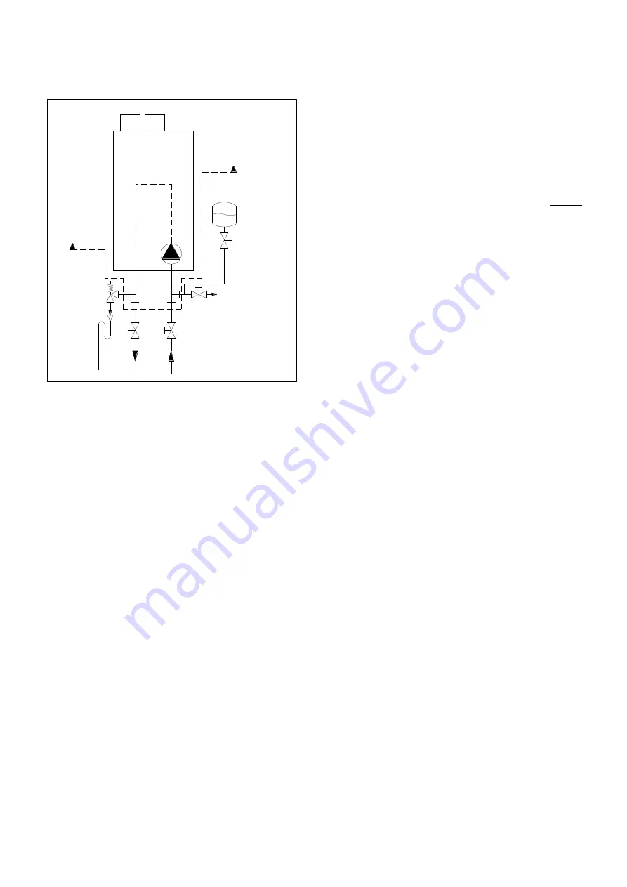
Two separate T-pieces are shipped with the boiler.
These are applied for externally mounting the pressure
relief valve and the boiler bleed valve for servicing the
boiler. We advise to install two service valves in the
flow and return pipes underneath the boiler, so the
boiler can be isolated from the heating system and
eventually disconnected, when needed.
When using a system pump, this pump should always
be mounted in the return pipe of the heating system.
Do not use chloride-based fluxes for soldering any
pipes of the water system.
6.4 The expansion vessel
The capacity of the expansion vessel must be selected
and based on the capacity of the central heating system
and the static pressure. Suggested is to fit the expan-
sion vessel in the return pipe of the central heating sys-
tem. It can be combined with the drain valve for service.
See the above drawing.
6.5 Pressure relief valve
The boiler has no internal pressure relief valve. This should be installed close to the boiler in the flow pipe of the
heating system. When having cascaded boilers, each boiler should have its own pressure relief valve. It is advised
to use the T-piece that is supplied with the boiler, for this.
Advice is always to install service valves, so the boiler can be isolated from the heating system, when needed.
Make sure that the pressure relief valve is mounted between the boiler and the service valves.
The specifications and size of the relief valve should be determined by the installer and must comply with all appli-
cable regulations and boiler capacity.
6.6 Bypass
The boiler has no internal bypass. When many thermostatic valves are being used, the system should have a by-
pass to allow an adequate flow when all thermostatic valves are closed. Instead of a bypass also a low-loss header
can be used for this function.
The boiler flow will also be influenced when a pipe of the heating system is frozen / blocked. Make sure all heating
pipes are free from the risk of frost. If there is the risk of freezing of the heating system, all the pipe section must be
insulated and/or protected with the help of a tracing.
6.7 Pump functionality
Controlling the pump:
The pump speed is controlled by a PWM signal provided by the burner controller at a value causing a Delta T
across the heat exchanger of 20°C at the whole burner modulation range.
When the boiler modulates down or up, also the pump speed decreases or increases, keeping delta T at 20°C until
it reaches the end of its modulation range.
Delta T monitoring:
The delta T monitoring parameters are active. A malfunctioning of the pump, burner controller or a high resistance
in the hydraulic system will cause a high Delta T and will therefore be detected by the burner controller. The display
shows “dT Block” or “FlowReturn dTfault”.
P1
supplied
with
boiler
supplied
with
boiler
BOILER
boiler bleed
valve for service
boiler service valves
pressure
relief valve
expansion
vessel
Summary of Contents for S-CB+ Series
Page 2: ......
Page 3: ......
Page 22: ...S CB Boiler Range Manual 22 ...
Page 39: ...S CB Boiler Range Manual 39 9 4Electrical schematics ...
Page 124: ...S CB Boiler Range Manual 124 ...


