background image

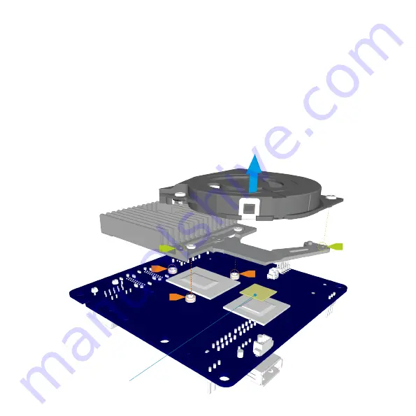
Prepare the NUC motherboard

Before  fitting  the  motherboard,  remove  the  stock  fan  and  cooler  which  is 
secured by 5 screws, 2 for the fan, 3 for the cooler. Clean any residual thermal 
paste from the CPU.

The chipset connects to the cooler assembly with a thermal pad, ensure that 
this remains on the chipset as it is ESSENTIAL for connecting to the Streacom 
cooler mount.

Thermal Pad

Summary of Contents for NCI

Page 1: ......

Page 2: ...en taken to ensure that it meets with the high standards that we have set for ourselves Should you have any questions that are not covered in this user guide support can be offered via email through our website at www streacom com We sincerely hope that you enjoy using our product ...

Page 3: ...NC1Overview 1 TopPanel Cooler 2 IntegratedPowerButton 3 BackPanel 4 AcrylicSidePanels 5 CoolerMount 6 FrontPanel 7 BottomPanel 8 VESA Mounts Optional 1 3 6 4 5 8 7 2 ...

Page 4: ...Removethebottompanel With the case turned upside down remove the 4 screws securing the bottom panelinplaceandliftoff ...

Page 5: ...Removethefront backandsidepanels Remove the front and back panels which are secured to the top panel by 4 screws 2 each With the front and back removed the side panels will be free to liftup ...

Page 6: ...oler which is secured by 5 screws 2 for the fan 3 for the cooler Clean any residual thermal pastefromthe CPU The chipset connects to the cooler assembly with a thermal pad ensure that this remains on the chipset as it is ESSENTIAL for connecting to the Streacom coolermount Thermal Pad ...

Page 7: ...thermal pad is located on the chipset IC then secure the cooler mount to the motherboard by the 3 screws as shown Do not over tighten the screws and ensure equal load is applied to all 3 screws sothatthecoolermountsitsflatagainstthe CPU Thermal Paste Thermal Pad ...

Page 8: ... motherboard apply thermal paste to its upper surface then secure the motherboard to the top panel using the 4 screws at each corner Ensure correct orientation of the motherboard by checking that themotherboardpowerswitchalignswiththetoppanelpowerbutton Thermal Paste ...

Page 9: ...s and position them in thetoppanelslots thensecurethefrontandbackpanelswiththe4screws If you are using internal WiFi the antenna should be fixed to the acrylic side panelsforoptimalperformance All other components such as RAM MSATA etc should be installed prior to fittingthebottompanel ...

Page 10: ...Fitthebottompaneltocompletethebuild With all components fitted all that remains is to fit the bottom panel using the 4 screwsshown Connect power videoandaccessories thenyouarereadytogo ...

Page 11: ...www streacom com V1 13 06 W ...

Reviews: