background image

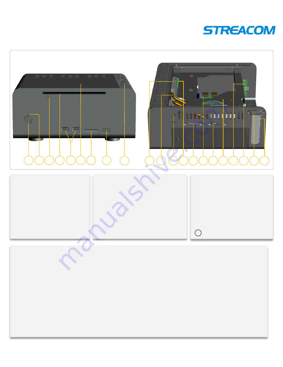
FC8 overview 

. IR Receive window 

.


Chassis heatsink side 

Side Panel’s Small Heat Block 

. Heatpipe 

. DC hole 

. IR receiver 

. eSATA cable 

. Card reader PCB board 

.

 eSATA expansion slot 

. HDD/ODD bracket 

. Power PCB board 

. HDD  anti-vibration circle


.

 PCI 

back-up block  

     . PCI slot 

. Power button 

. Power blue LED 

. ODD button 

. Slot of ODD 

. USB port  

. TOP panel 

. Card reader 

3  4 

13 

12 

14  15 

21 

18 

20 

19 

Model:                     FC8-2 
Material:                 100% full Aluminum  
Color

                   Silver / black / Gold 

Motherboard

       Mini ITX  

HDD drive bay


1x2.5” +1X3.5’’ HDD drive bay  

ODD drive bay

    an ultra-thin standard slot-in optical drive 

Front I/O Port

      2

×

USB ports   

Card Reader

       Multi-card Reader  

Cooling

               Heatpipe 

Dimension

          240mm

×

250mm

×

100mm (L

×

W

×

H) 

Power Supply

     Optional build in DC power  

Remote control

   Optional the MCE remote control built-in IR receiver  

Net Weight

          2.6KG 

16  17 

10  11 

21 

Summary of Contents for FC8

Page 1: ...FC8 WESENA STREACOM Computer Chassis Installation Guide more infomations browse our web www streacom com ...

Page 2: ...T FC8 overview 3 Open the Top panel 4 Motherboard installation 4 Heatsink System Installation 5 HDD installation 7 ODD installation 7 PCI PCIE installation 8 Close Top panel 9 PCB cables reference diagram 10 ...

Page 3: ... USB port TOP panel Card reader 1 3 4 7 2 5 8 6 13 12 14 15 21 18 20 19 Model FC8 2 Material 100 full Aluminum Color Silver black Gold Motherboard Mini ITX HDD drive bay 1x2 5 1X3 5 HDD drive bay ODD drive bay an ultra thin standard slot in optical drive Front I O Port 2 USB ports Card Reader Multi card Reader Cooling Heatpipe Dimension 240mm 250mm 100mm L W H Power Supply Optional build in DC pow...

Page 4: ...et Show as pictures Remove CPU cooling panels Remove 4pcs CPU cooling panels take out CPU cooling panels Show as pictures Motherboard installment Put the I O baffle plate in Show as pictures Open top plate Take off 4 top plate screws and take out the top plate Show as pictures ...

Page 5: ...ct DC connector insert power connect the power line and IR line etc Show as pictures Put the DC connector power and other electronic components Install CPU nut Tearing off the double faced adhesive tape protecting paper on CPU nut Pressing CPU nut on motherboard cooling hole from motherboard s underside Pressing other 3pcs CPU nut Show as pictures ...

Page 6: ...as pictures Installing heatsink pipes Wearing thermal grease on the tangent surface between CPU and motherboard cooling panels Locking CPU shrapnel and motherboard Put heatsink pipes on cooling panels U bay Show as pictures Installing heatsink pipes Coving motherboard cooling panels up Locking 4 screws Show as pictures ...

Page 7: ... accessories bag Alignment hole and lock Show as pictures ODD installment Put ODD on the ODD bracket Alignment and lock screws Show as pictures 2 5 inch HDD installment installation for your need Install 2 5 inch HDD lock the 3 HDD screws PM3 5 show as photos Show as pictures ...

Page 8: ...acket which have been insert lines into the right place of case To correct of all the lines connection Install the ODD button secondly and then put the bracket in the case by its sideway Alignment hole and lock screws Show as pictures PCI or PCIE installment Exit screws firstly take out the baffle plate and plate locking piece Put the PCI or PCIE expand card in and then put the plate locking piece...

Page 9: ... plate Check the installation place and the connectors again after finishing the inner installation Arrange Flat Cable in case in order to avoid block CPU fan and cooling fan And cover the top plate Show as pictures ...

Page 10: ...WESENA STREACOM Thankyou for using our Products more infomations browse our web www streacom com ...

Reviews: