background image

AC Power and HVAC Service Requirements


Electrical Power Planning

3-5

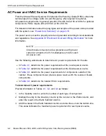
AC Power Outlet Requirements

If you 

do

 use a pair of PDUs in the cabinet, use Tables 

3-5

 and 

3-6

 to determine the 

total number of power outlets required 

outside the cabinet

1. In the Quantity column, write the number of each type of component.

2. Multiply the value in the Quantity column by the value in the Outlets column, and 

enter the total in the Subtotal column.

3. Add the values in the Subtotal column and enter the sum next to TOTAL NUMBER 

OF A-SIDE POWER OUTLETS and TOTAL NUMBER OF B-SIDE POWER 
OUTLETS.

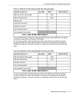
Table 3-5. Worksheet: A-Side External Power Outlet Requirements: PDUs Used

Component

Quantity

Outlets

Subtotal

PDUs

x

1

Other external components

TOTAL NUMBER OF A-SIDE POWER OUTLETS

Table 3-6. Worksheet: B-Side External Power Outlet Requirements: PDUs Used

Component

Quantity

Outlets

Subtotal

PDUs

x

1

Other external components

TOTAL NUMBER OF B-SIDE POWER OUTLETS

Summary of Contents for ftServer 2500

Page 1: ...Stratus Technologies R609 04A Stratus ftServer 2500 4400 and 6200 Systems Site Planning Guide ...

Page 2: ...is document may be copied reproduced or translated either mechanically or electronically without the prior written consent of Stratus Technologies Stratus the Stratus logo ftServer and the ftServer logo are registered trademarks of Stratus Technologies Bermuda Ltd The Stratus Technologies logo the Stratus 24 x 7 logo ActiveService ftScalable and Active Upgrade are trademarks of Stratus Technologie...

Page 3: ...ements 2 4 3 Electrical Power Planning 3 1 Redundant Power Sources 3 1 AC Power and HVAC Service Requirements 3 2 AC Power Outlet Requirements 3 5 Connecting a System Directly to Two Separate AC Power Sources 3 7 Selecting a UPS Unit for ftServer Systems Windows Systems 3 10 Communicating with a UPS over a Network 3 12 Connecting Power to Systems PDUs and a UPS 3 12 Connecting a System Directly to...

Page 4: ...ements for Brazil 5 11 6 Rack Configuration Planning 6 1 Using PDUs 6 1 Determining PDU Requirements 6 2 Sample PDU Usage Calculation 6 4 Appendix A System Specifications A 1 Pedestal System Specifications A 1 Rack Mountable System Specifications A 7 AAP86900 and AAP87600 PDU Specifications A 12 Appendix B Electrical Circuit and Wiring Information B 1 Fault Protection Requirements B 1 Grounding Co...

Page 5: ...Contents Contents v Index Index 1 ...

Page 6: ...Connections to an ftScalable Storage System 5 5 Figure A 1 Pedestal ftServer 2500 or 4400 System Front View A 2 Figure A 2 Pedestal ftServer 2500 or 4400 System No VTMs Rear View A 3 Figure A 3 Pedestal ftServer 2500 or 4400 System With VTMs Rear View A 4 Figure A 4 Rack Mountable ftServer 2500 4400 or 6200 System Front View A 7 Figure A 5 Rack Mountable ftServer 2500 4400 or 6200 System With VTMs...

Page 7: ...Side External Power Outlet Requirements No PDUs 3 6 Table 3 9 APC Symmetra Models for PDUs or for Multiple Systems 3 10 Table 3 10 APC UPS Models for a Single Rack Mountable System 3 11 Table 3 11 APC UPS Models for a Single Pedestal System 3 11 Table 3 12 Power Cords Between ftServer Systems and Peripheral Components and AC Power 3 16 Table 3 13 Power Cords Between ftServer Systems or Storage Sys...

Page 8: ...able A 1 Pedestal ftServer 2500 or 4400 System Specifications A 5 Table A 2 Cabinet Dimensions A 9 Table A 3 Rack Mountable ftServer 2500 4400 and 6200 Systems Specifications A 10 Table A 4 AAP87600 and AAP86900 PDU Specifications A 14 Table B 1 Connectors for AC Power Outlets B 8 Table C 1 Compliance Standards for ftServer 2500 4400 and 6200 Systems C 2 ...

Page 9: ...mation about Modem Requirements for Brazil on page 5 11 Notation Conventions This document uses the notation conventions described in this section Warnings Cautions and Notes Warnings cautions and notes provide special information and have the following meanings W A R N I N G A warning indicates a situation where failure to take or avoid a specified action could cause bodily harm or loss of life C...

Page 10: ...er documentation You can access StrataDOC at the http stratadoc stratus com Web site A copy of the StrataDOC CD ROM for your system is included with this release To order additional copies of the StrataDOC CD ROM or to obtain copies of printed manuals do one of the following If you are in North America call the Stratus Customer Assistance Center CAC at 800 221 6588 or 800 828 8513 24 hours a day 7...

Page 11: ...ve your questions with the help available at these online sites and the ftServer system is covered by a service agreement please contact the Stratus Customer Assistance Center CAC or your authorized Stratus service representative For information about how to contact the CAC see the http www stratus com support cac Web site Commenting on the Documentation To provide corrections and suggestions on t...

Page 12: ...Preface xii Stratus ftServer 2500 4400 and 6200 Systems Site Planning Guide R609 ...

Page 13: ...afety Notices on page 1 12 Site Planning Overview Site planning for fault tolerant systems includes Purchasing an appropriate cabinet and monitor If you do not purchase a monitor from Stratus provide a monitor that meets the system s requirements N O T E S 1 A monitor keyboard and mouse are required to install ftServer System Software ftSSS 2 After you install VMware ESX and ftSSS software the mon...

Page 14: ...tem through a serial connection After you install the operating system and ftSSS at times you may be unable to use the monitor mouse and keyboard directly attached to the system Rack space planning Ensure that the power distribution units PDUs supply sufficient power to the components you have purchased and that you have sufficient space available in an appropriate cabinet Use the Site Planning Ch...

Page 15: ...nclosure and continues to operate normally The only consequences are that the system is less fault tolerant and any I O throughput distributed between the enclosures may be reduced To restore full fault tolerance an enclosure can be replaced without taking the system offline ftServer systems can connect to the ActiveService Network ASN Connecting a system to the ASN allows the CAC or your authoriz...

Page 16: ...ccessfully due to disconnections If you must use a PBX do not route the telephone extension through a switchboard instead provide a direct dial analog number Do you have an additional telephone connection and telephone near the operator s station for voice communications when calling for support Planning for Network Connectivity The system contains four embedded 10 100 1000 megabits per second Mbp...

Page 17: ...s 2 An ftServer system that runs the Windows operating system or VMware ESX software supports ftScalable Storage systems and EMC CLARiiON and Symmetrix storage systems Will your system connect to external Fibre Channel storage enclosures in a storage area network SAN configuration If so do you have a minimum of two switches that can accommodate the cables from the pair of Fibre Channel HBAs in eac...

Page 18: ...f the power cords that are provided for the PDUs or system and optional components What type of AC receptacles do you need to provide Is the AC power service wired properly Planning Space for Your System Will your system and its external components fit where you plan to place them If you are rack mounting the system what is the height of the cabinet you will use and what is the total height of the...

Page 19: ...planning Have you reviewed and discussed the requirements with the facilities personnel and contractors to ensure that all site modifications are understood and implemented If you have any questions about the number and types of components contact your Stratus account representative or distributor System Documentation Table 1 2 lists the documents for all ftServer 2500 4400 and 6200 systems and th...

Page 20: ...0 Systems Operation and Maintenance Guide R610 Start up shut down and operate your system Troubleshoot system hardware Remove and replace CRUs including PCI adapters Stratus ftServer 2500 4400 and 6200 Systems Installation Guide R611 Install your system including mounting the system in a cabinet Install ftSSS and the operating system on your new system Configure VTMs if present Start the system fo...

Page 21: ...nificant known problems and how to work around or avoid the problems Stratus ftServer System Software Installation and Configuration for Windows Systems R002W Respond to Mini Setup questions Install or reinstall ftSSS and Windows Server software Upgrade software and BIOS BMC and VTM firmware Configure ftSSS Set up your system to communicate with a UPS Stratus ftServer System Administrator s Guide ...

Page 22: ...oftware release Learn the latest information about the product Learn about significant known problems and how to work around or avoid the problems Stratus ftServer System Administrator s Guide for the Linux Operating System R003L Use tools that are provided by the operating system software ftServer System Software and other vendors to manage and troubleshoot the system Install and upgrade the Linu...

Page 23: ... and upgrade VMware ESX Install and upgrade ftSSS and BIOS and BMC firmware Manage data storage devices Release Notes Stratus ftServer System Software for VMware vSphere R001E Learn the contents of the latest ftServer System Software release Learn the latest information about the product Learn about significant known problems and how to work around or avoid the problems VMware iSCSI SAN Configurat...

Page 24: ...t even when only one power cord is connected W A R N I N G To prevent a cabinet from tipping over and injuring a person or damaging the system start installing systems from the bottom of the cabinet upward W A R N I N G If you replace the modem cable supplied by Stratus use a cable with a gauge of at least 26 AWG to prevent fire W A R N I N G To avoid fire electric shock and equipment breakdown pr...

Page 25: ...a place that meets the requirements specified in this guide Avoid the following conditions to avoid the risk of fire Dust High humidity such as a place near a boiler Direct sunlight Instability such as places not stabilized against earthquakes W A R N I N G Do not use or store this product in a corrosive environment Avoid using or storing this product in an environment which may contain corrosive ...

Page 26: ... install or remove any internal device or connect or disconnect any interface cables to or from the server Even if the server is powered off but still connected to a power source touching an internal device cable or connector may cause an electric shock or a fire resulting from a short circuit W A R N I N G Do not disassemble repair or alter the server except as described in the Stratus ftServer 2...

Page 27: ...erver 2500 4400 and 6200 Systems 1 15 W A R N I N G Do not leave the DVD tray ejected Dust may enter the equipment and cause it to malfunction The ejected tray may also become a cause of injuries W A R N I N G W A R N I N G W A R N I N G ...

Page 28: ...Safety Notices 1 16 Stratus ftServer 2500 4400 and 6200 Systems Site Planning Guide R609 W A R N I N G W A R N I N G W A R N I N G W A R N I N G ...

Page 29: ...Safety Notices Site Planning for ftServer 2500 4400 and 6200 Systems 1 17 W A R N I N G ...

Page 30: ...Safety Notices 1 18 Stratus ftServer 2500 4400 and 6200 Systems Site Planning Guide R609 ...

Page 31: ...patible with the maximum ambient temperature Tma specified by the manufacturer Reduced Air Flow Installation of the equipment in a rack should be such that the amount of air flow required for safe operation of the equipment is not compromised Mechanical Loading Mounting of the equipment in the rack should be such that a hazardous condition is not achieved due to uneven mechanical loading Circuit O...

Page 32: ...nagement brackets are provided to support and constrain data and power cords so that the cables do not interfere with air flow out of the rear of the enclosures and so that the connectors do not disconnect or break To prevent stray voltages all components are grounded together through the vertical mounting rails to the cabinet frame and then to local building ground To ensure signal quality use a ...

Page 33: ...Figure 2 1 shows the required rail clearance between the front vertical rails and the inside edge of an accessory leg Figure 2 1 Rail Clearance 1 Front vertical EIA rail 2 Accessory leg 3 Front of cabinet 0 5 inch 1 27 cm minimum 0 5 inch minimum msys182 1 2 3 ...

Page 34: ...n about the alternative method for directly connecting to ftServer systems running VMware ESX Management PC Requirements For ftServer systems running ftSSS for VMware vSphere you must provide a computer to be the management PC The computer must have A serial port Terminal emulation software installed The emulator must be able to transmit keystrokes such as F1 and F2 to interact with the BIOS A ser...

Page 35: ...stems require at least two separate and independent AC power sources an A side power source and a B side power source that provide power to the system s power receptacles labeled A and B respectively Either source must be capable of continuing to provide power if power to the other source is lost The A side power source provides power to one side of each system and storage enclosure as well as to ...

Page 36: ...t provide a protective earth ground current at a maximum of 3 5 milliamperes mA for each AC power cord Use the following worksheets to determine AC power requirements for the site In Table 3 1 determine the power requirements at the A side power source In Table 3 2 determine the power requirements at the B side power source In Table 3 3 determine the power requirements for components outside of th...

Page 37: ...e power requirements for the switch Two switches are required for fault tolerant operation Connect one switch to A side power and the other switch to B side power x User supplied components TOTAL A SIDE POWER REQUIREMENTS Table 3 2 Worksheet Determining B Side Power Requirements System Component Quantity Watts Watts Subtotal ftServer 2500 or 4400 system x500 ftServer 6200 system x850 Storage enclo...

Page 38: ...nter the value in the Total Watts column of Table 3 4 2 Multiply the value in the Total Watts column by 3 41 and enter the number of BTUs in the BTUs hr Subtotal column Table 3 3 Worksheet Determining External Power Requirements System Component Watts Other peripheral components TOTAL EXTERNAL POWER REQUIREMENTS Table 3 4 HVAC Requirements Total Watts From Tables 3 1 3 2 and 3 3 Convert to BTUs BT...

Page 39: ...in the Outlets column and enter the total in the Subtotal column 3 Add the values in the Subtotal column and enter the sum next to TOTAL NUMBER OF A SIDE POWER OUTLETS and TOTAL NUMBER OF B SIDE POWER OUTLETS Table 3 5 Worksheet A Side External Power Outlet Requirements PDUs Used Component Quantity Outlets Subtotal PDUs x 1 Other external components TOTAL NUMBER OF A SIDE POWER OUTLETS Table 3 6 W...

Page 40: ...Add the values in the Subtotal column and enter the sum next to TOTAL NUMBER OF A SIDE POWER OUTLETS and TOTAL NUMBER OF B SIDE POWER OUTLETS Table 3 7 Worksheet A Side External Power Outlet Requirements No PDUs Component Quantity Outlets Subtotal ftServer systems x 1 Storage enclosures x 1 LCD monitor units or external monitors x 1 Tape drive enclosure x 1 Other peripheral components TOTAL NUMBER...

Page 41: ...een the two power sources the less likely they will both fail at the same time Due to redundancy in ftServer systems power to either side of the system keeps the system in operation although the system is no longer fault tolerant with regard to power Figure 3 1 shows how to connect rack mounted ftServer 2500 4400 and 6200 systems directly to two separate AC power sources Figure 3 2 shows how to co...

Page 42: ...tus ftServer 2500 4400 and 6200 Systems Site Planning Guide R609 Figure 3 2 Pedestal System Connected Directly to AC Power 1 A side system power cord 2 B side system power cord 3 AC power outlets 4 Circuit breakers maximum of 20A asys002 1 3 2 4 3 4 ...

Page 43: ...ical Power Planning 3 9 Figure 3 3 PDUs Connected Directly to AC Power 1 A side PDU 2 B side PDU 3 B side jumper cables 4 A side jumper cables 5 PDU power cords 6 AC power outlets 7 Circuit breakers maximum of 20A 5 4 7 7 5 2 asys003a 3 1 3 4 6 6 ...

Page 44: ...perating system should shut down in response to certain signals from the UPS and the UPS may unnecessarily shut down the system If you have a situation that requires the use of a UPS for example if you do not have two separate power sources at the installation site use the tables in this section to select an appropriate UPS do not use UPS signaling and contact the CAC or your authorized Stratus se...

Page 45: ...Nominal Voltage AC Power Output North America Model SUA1500RM2U 120V 120V Japan Model SUA1500RMJ2U 100V 100V Rest of the world Model SUA1500RMI2U 230V 120V or 208V Table 3 11 APC UPS Models for a Single Pedestal System Locale Smart UPS Nominal Voltage AC Power Output North America Model SUA1500 120V 120V or 208V Japan Model SUA1500J 100V 100V Rest of the world Model SUA1500I 230V 230V or 240V Tabl...

Page 46: ...all your ftServer system download PowerChute Network Shutdown from APC and install and configure the tool on the system as described in the Stratus ftServer System Software Installation and Configuration for Windows Systems R002W PowerChute Network Shutdown monitors the UPS for an imminent power loss and initiates a shutdown of the system before power is lost Connecting Power to Systems PDUs and a...

Page 47: ...Power Cord Connections for Systems PDUs and a UPS 1 A side PDU 2 B side PDU 3 B side system power cables black 4 A side system power cables gray 5 PDU power cords 6 UPS 7 UPS power cord 8 AC power outlets 9 AC power mains distribution circuit breaker maximum of 20A 8 8 5 4 7 5 2 asys003 9 9 3 1 3 4 6 ...

Page 48: ...ctly to a UPS You can connect the A side power connectors of your system directly to a UPS as shown in Figure 3 5 and Figure 3 6 Figure 3 5 Rack Mountable Systems A Side Power Connected Directly to a UPS 1 B side system power cord 2 A side system power cord 3 UPS 4 UPS power cord 5 AC power outlets 6 Circuit breakers maximum of 20A 3 6 6 4 5 5 1 asys004 2 ...

Page 49: ...out of the way of foot traffic Power cords described as Domestic are made with American Wire Gauge AWG cordage and are intended for use in North America Refer to UL 62 and CSA C22 2 No 49 All other power cords are made with International Harmonized cordage and are intended for use in the specified countries and other countries that use that standard 1 B side system power cord 2 A side system power...

Page 50: ...d 15A 127V 7 ft North America Domestic B50104F NEMA 5 15 UL CSA approved 15A 127V 15 ft North America Domestic B50112F CEE 7 VII 16A 250V 4 5m Europe Continental B50116F BS 1363 A 13A 250V 4 5m United Kingdom B50124F AS NZS 3112 1993 10A 250V 4 5m Australia B50140F SEV 1011 S24507 10A 250V 4 5m Switzerland B50152F SABS164 1 1992 ZA 3 13A 250V 4 5m South Africa India B50153F IEC 60309 TUV approved ...

Page 51: ...rth America locking power cord B50301F 45M IEC 60320 C14 to IEC 60320 C13 10A 250V 4 5m International B50174 P L6 20P PSE approved 15A 250V 15 ft Japan locking power cord 200V applications Table 3 14 Power Cords to Connect PDUs Directly to AC Power Mains Marketing ID Plug Type Rating Length Locale B50154F IEC 60320 C19 to IEC 60309 20A 250V 15 ft International B50171F IEC 60320 C19 to NEMA L6 20P ...

Page 52: ...reference ground over independent ground connections to the cabinet frame Ensure that a high integrity safety ground conductor is installed as part of the wiring system See Grounding Considerations on page B 1 for a more complete discussion of ftServer system grounding Table 3 16 System Power Jumper Cables to Connect ftServer Systems to PDUs Marketing ID Plug Type to System Plug Type to PDU Rating...

Page 53: ...humidistat to monitor room temperature and humidity See Chapter 3 Electrical Power Planning for detailed information about HVAC planning Is as free of dust as possible meeting at a minimum ISO 14644 1 class 8 standards for a clean room environment Dust buildup in the system can impede air circulation and heat transfer causing components to become less reliable as the ambient temperature rises Fans...

Page 54: ...ve power receptacles telephone jacks and other connection points Provides communications cable connectors or patch panels as needed Provides two electrically separate grounded AC wall outlets within reach of the power cords from the system or PDUs and if used UPS units Detachable power cords are 12 ft 3 65m If the power cord must be hard wired consult an electrician to plan the length of the power...

Page 55: ... not connect to a PDU N O T E ftSSS for the Linux Operating System and ftSSS for VMware vSphere do not support the use of a UPS For optional components AC wall outlets within reach of the power cords from the components or use PDUs Make sure that cables you plan to connect to the system are long enough to reach between the system and external components or connections For information about specifi...

Page 56: ...Planning for Cables 4 4 Stratus ftServer 2500 4400 and 6200 Systems Site Planning Guide R609 ...

Page 57: ...nections VMware ESX Systems on page 5 9 Telephone Line Connections on page 5 9 Site Planning for Systems in an ftGateway Group on page 5 10 Modem Requirements for Brazil on page 5 11 N O T E S 1 Software upgrade services are available from Stratus Professional Services For a list of available services see http www stratus com services ps offerings htm 2 If you have a unique network requirement con...

Page 58: ...tra320 SCSI PCI Adapters for connection to tape drives Table 5 1 lists the available SCSI cables and Figure 5 1 illustrates the connections from two systems to a tape drive enclosure with two tape drives Figure 5 1 SCSI Connections to Tape Drives Table 5 1 Single initiated SCSI Tape Cables Length Part number 10 ft 3 05m AW 001046 01 30 ft 3 05m AW 001046 02 rsys054 System System Tape ...

Page 59: ...nt from one or two ftServer systems to the RAID controller tray of an ftScalable Storage system Attachment through a SAN from multiple ftServer systems to ftScalable Storage systems ftSSS for VMware vSphere supports the following attachments Direct attachment from one ftServer system to the RAID controller tray of an ftScalable Storage system Attachment through a storage area network SAN from mult...

Page 60: ...systems and storage enclosures Figure 5 2 illustrates Fibre Channel connections from a single system to a switch and from the switch to the ftScalable Storage controller tray Connections to EMC storage systems through a SAN are similar Figure 5 3 illustrates Fibre Channel connections directly between an ftServer system and an ftScalable Storage controller tray Direct connections to EMC storage sys...

Page 61: ...ions Line Planning 5 5 Figure 5 3 Direct Attach Fibre Channel Connections to an ftScalable Storage System wom031 CPU I O Enclosure 10 CPU I O Enclosure 11 ftScalable Storage RAID Controller Tray 2 ftScalable Storage RAID Controller Tray 1 ...

Page 62: ... not support VTMs You must supply Ethernet cables for the following From two or four embedded Ethernet ports on the system and Ethernet ports on U574F LC or U575F Ethernet adapters to network connection points N O T E Two Ethernet ports are typically paired and teamed in software for fault tolerance Each member of the pair requires an Ethernet cable From each ftScalable Storage RAID controller tra...

Page 63: ...the EIA TIA 568 A or EIA TIA 568 B standard For connections to an Ethernet hub or switch provide a straight through cable For 100 or 1000 Mbps fast Ethernet operation provide full duplex or Category 5 Ethernet cables System Ethernet port 2 or 4 U575F Two Port Copper 10 100 1000 Base T Ethernet PCI Adapter gigabit copper adapter for servers 1 for each port typically teamed for fault tolerance U574F...

Page 64: ...re that your ftServer system provides adequate bandwidth for your iSCSI storage requirements ftScalable Storage RAID controller tray 3 two for each controller tray and one to a management PC N A You must supply these cables 24 AWG Unshielded Twisted Pair UTP EIA TIA Verified Category 3 or Category 5 wire with RJ 45 modular connectors terminated with pair wiring adhering to the EIA TIA 568 A or EIA...

Page 65: ...ephone line to connect the ASN modem if used to a telephone connection point A 7 ft 2 13m telephone cable is shipped with the modem assembly 1 N O T E A dedicated phone line provides the most reliable service for ASN connections ASN calls routed through a PBX might be slow due to the load on the PBX or might not complete successfully because the calls can become disconnected If you must use a PBX ...

Page 66: ... in an ftGateway Group N O T E ftSSS for VMware vSphere does not support ftGateway groups Multiple ftServer systems at a site can share a single telephone connection to the ASN by implementing an ftGateway group Unless VTMs are installed in each system the systems in the group must be connected to a single physical Ethernet subnetwork One system acts as a gateway for ASN connectivity This gateway ...

Page 67: ...level of manageability by allowing the system to be serviced even when the operating system is not operational N O T E S 1 You cannot mix VTMs and ftServer Access Adapters in the same ftGateway group ftServer Access Adapters are system management adapters used in earlier models of ftServer systems 2 Make sure that only layer 1 and layer 2 devices separate the gateway and slave systems During a con...

Page 68: ...Modem Requirements for Brazil 5 12 Stratus ftServer 2500 4400 and 6200 Systems Site Planning Guide R609 ...

Page 69: ... you do have a support agreement with Stratus use pairs of PDUs to provide AC power to systems and components in a cabinet if six or more power cords would otherwise exit from the cabinet The A side top PDU provides power to The A side of each system A rack mounted LCD monitor unit An ftScalable Storage system Any rack mounted tape drive enclosures The B side bottom PDU provides power to the other...

Page 70: ...ent that the ftServer systems and rack mounted components will draw and whether you need a second pair of PDUs To complete Table 6 1 1 Obtain the voltage available at your location Consult a facilities manager at your site to make sure you know the correct voltage 2 For each type of component you plan to place in the rack calculate the required current as follows Divide the wattage of the element ...

Page 71: ...For each component add 1 to the value in the space above and write the result 4 In column 4 write the cumulative current required For each component add the current for the component which you entered in Table 6 1 to the value in the space above and write the result You need another pair of PDUs if the cumulative number of outlets exceeds 8 or if the cumulative current exceeds 15A Use the informat...

Page 72: ...omponents were added one by one calculating The total current demanded by the components The total space used in the rack The total number of outlets required Table 6 3 Sample Current and Rack Space Requirements Component Watts Current A Rack Space ftServer 6200 system 850 4 21 4U 1U LCD monitor unit 54 0 13 1U EC SL1AA YF tape drive enclosure 80 0 48 2U ftScalable Storage system 400 2 4 2U Table ...

Page 73: ...sure one ftScalable Storage system and two ftServer 6200 systems This set of components consumes 13 43 amperes Adding another system would increase the consumption to 18 53 amperes exceeding the capacity of the A side PDU To add any more components you require another pair of PDUs The configuration also occupies five outlets in the PDU and 15U of rack space ...

Page 74: ...Sample PDU Usage Calculation 6 6 Stratus ftServer 2500 4400 and 6200 Systems Site Planning Guide R609 ...

Page 75: ...are provided in the Stratus ftServer Systems Peripherals Site Planning Guide R582 Pedestal System Specifications The following figures show front and rear views of the systems Figure A 1 shows the front of a pedestal ftServer 2500 or 4400 system its bezel pulled forward Figure A 2 shows the rear of a pedestal ftServer 2500 or 4400 system with no VTMs specifying the locations of the connectors at t...

Page 76: ...Pedestal System Specifications A 2 Stratus ftServer 2500 4400 and 6200 Systems Site Planning Guide R609 Figure A 1 Pedestal ftServer 2500 or 4400 System Front View asys006a ...

Page 77: ... 2 Pedestal ftServer 2500 or 4400 System No VTMs Rear View 1 Ports on a PCI adapter in slot 1 2 System 10 100 1000 Mbps Ethernet ports 4 3 USB ports 3 4 VGA monitor port 5 Serial COM ports 2 6 Modem and telephone cord port 7 Power receptacles 2 asys007a 2 4 3 7 5 1 6 ...

Page 78: ...9 Figure A 3 Pedestal ftServer 2500 or 4400 System With VTMs Rear View 1 Ports on a PCI adapter in slot 1 2 System 10 100 1000 Mbps Ethernet ports 4 3 USB ports 3 4 VGA monitor port 5 Serial COM ports 2 6 Telephone cord port 7 Power receptacles 2 8 VTM 10 100 Mbps Ethernet port 2 asys007 2 4 3 7 5 8 1 6 ...

Page 79: ...g Environmental Operating temperature 41 F to 95 F 5 C to 35 C For every 800 ft 243 8m above 2 000 ft 609 6m lower the maximum operating temperature 35 C by 1 C Storage temperature 38 F to 140 F 40 C to 60 C Operating altitude 0 ft to 10 000 ft 0m to 3 048m Maximum rate of temperature change during operation 12 C per hour Relative humidity during operation 20 to 80 noncondensing Relative humidity ...

Page 80: ...or each VTM VTMs are optional components on Windows and Linux systems so the Ethernet ports for them are not functional if VTMs are not present VTMs are not present on ftServer systems running VMware ESX Disk drives To boot from internal disks one Serial Attached SCSI SAS for boot disks and optionally two SAS or Serial ATA SATA disk drives for data in each CPU I O enclosure NOTE ftServer systems r...

Page 81: ... rear of a rack mountable ftServer 2500 4400 or 6200 system specifying the locations of the connectors at the rear of the system Table A 2 lists the dimensions of the cabinets supplied by Stratus Table A 3 lists the specifications for the ftServer 2500 4400 and 6200 systems See Table A 4 for the specifications of the PDU and the Stratus ftServer Systems Peripherals Site Planning Guide R582 for the...

Page 82: ...tem 10 100 1000 Mbps Ethernet ports 4 3 USB ports 3 4 VGA monitor port 5 Serial COM ports 2 6 Power receptacles 2 7 VTM 10 100 Mbps Ethernet ports 2 VTMs are optional components on Windows and Linux systems so the Ethernet ports for them are not functional if VTMs are not present VTMs are not present on ftServer systems running ftSSS for VMware vSphere 8 Modem and telephone cord port asys010 6 7 4...

Page 83: ...th 41 in 1 04m Depth 53 in 1 35m 24U Cabinet Height including casters 50 in 1 27m Width 27 5 in 70 cm Depth 41 in 1 04m Weight empty 275 lb 125 kg Weight empty with pallet and shipping container 436 lb 197 8 kg Weight capacity 1500 lb 559 9 kg 38U Cabinet Height including casters 74 in 1 9m Width 27 5 in 70 cm Depth 41 in 1 04m Weight empty 344 lb 156 kg Weight empty with pallet and shipping conta...

Page 84: ...crews and bezel Weight including 6 DIMMS 4 processors and 6 disks Two enclosures 110 lb 49 9 kg fully loaded Rails and shelf unit 13 8 lb 6 26 kg Environmental Operating temperature 41 F to 95 F 5 C to 35 C For every 800 ft 243 8 m above 2000 ft 609 6 m lower the maximum operating temperature by 1 C Storage temperature 38 F to 140 F 40 C to 60 C vented Operating altitude 0 ft to 10 000 ft 0m to 3 ...

Page 85: ... X 64 bit 133MHz slot Two full height capable slots one PCI Express x4 connector 2 5Gbps slot and one PCI X 64 bit 133MHz slot and one low profile PCI X 64 bit 133 MHz slot VTM An advanced system management module card When VTMs are installed a 10 100 Mbps Ethernet port dedicated to the VTM is present for each VTM VTMs are optional components on Windows and Linux systems so the Ethernet ports for ...

Page 86: ...PDU Figure A 6 AAP86900 PDU DVD RW drive In each CPU I O enclosure one combo drive that reads from and writes to CDs and DVDs NOTE ftServer systems running VMware ESX support the DVD drive only during the initial software installation process and maintenance periods For more information about explicitly enabling this drive after installation see the Stratus ftServer System Administrator s Guide fo...

Page 87: ...AAP86900 and AAP87600 PDU Specifications System Specifications A 13 Figure A 7 AAP87600 PDU 1 Power switch 2 Power receptacle pdu007 1 2 3 ...

Page 88: ...sions Height 1 75 in 4 45 cm Width 19 1 in 48 51 cm Depth 6 75 in 17 15 cm Environmental Operating temperature during operation 41 F to 95 F 5 C to 35 C For every 800 ft 243 8m above 2000 ft 609 6m lower the maximum operating temperature 95 F 35 C by 1 8 F 1 C Maximum rate of temperature change during operation 12 C per hour or 0 2 C per minute Relative humidity during operation 10 to 80 nonconden...

Page 89: ... PDUs Grounding Considerations The system obtains an earth reference ground through the power cords attached to the system Similarly each peripheral device connected to the system obtains ground through its power cord For each peripheral device you must ensure that a high integrity safety ground conductor is installed as part of the wiring system in accordance with U S national electric code NFPA ...

Page 90: ...w the hot ground and or neutral AC signals should be connected to the power input plug to the system and optional components Figure B 3 illustrates a single phase 120V AC circuit connection Figure B 4 illustrates a single phase 240V AC circuit connection Figure B 5 illustrates a split phase 120 240V AC circuit connection Figure B 6 illustrates a three phase 208V AC Y or source circuit connection p...

Page 91: ...cations both X and Y can be electrically hot with respect to the system base earth reference ground Figure B 2 shows the physical locations of the X and Y inputs on the system base Figure B 2 Power Input Labeling Figure B 3 shows a single phase 120V AC circuit connection Note that this application requires a single pole circuit breaker Figure B 3 Single Phase 120V AC Circuit Connection Power input...

Page 92: ... Figure B 4 shows a single phase 240V AC circuit connection Note that this application requires a single pole circuit breaker Figure B 4 Single Phase 240V AC Circuit Connection Circuit A or B X Y G PE To power input A or B Wall Power Cord L N G PE 0V Single system 20A maximum 240V PDU 20A maximum ...

Page 93: ...phase 120 240V AC circuit connection Note that this application requires a double pole circuit breaker Figure B 5 Split Phase 120 240 Volts AC Circuit Connection Circuit A or B X Y G PE To power input A or B Wall Power Cord L1 L2 N G PE 240V 120V 0V 120V Single system 20A maximum PDU 20A maximum ...

Page 94: ...urce connection Note that the X and Y inputs on the system can be connected from L1 and L2 L2 and L3 or L1 and L3 This application requires a double pole circuit breaker Figure B 6 Three Phase 208V AC Y or D Source Circuit Connection Phase to Phase Circuit A or B 120V X Y G PE To power input A or B Wall Power Cord L1 L2 L3 N G PE 208V 208V 120V 0V 120V Single system 20A maximum PDU 20A maximum ...

Page 95: ...l source connection Note that the system s X input can be connected to L1 L2 or L3 This application requires a single pole circuit breaker Figure B 7 Three Phase 380V AC Y or D Source Circuit Connection Phase to Neutral Circuit A or B 220V X Y G PE To power input A or B Wall Power Cord L1 L2 L3 N G PE 220V 380V 380V 220V 0V Single system 20A maximum PDU 20A maximum ...

Page 96: ...wer cords that Stratus supplies with ftServer systems and optional devices Table B 1 Connectors for AC Power Outlets Connector Configuration Rating Description NEMA L6 20 20A 250 volts AC 2 pole 3 wire NEMA 5 15 15A 125 volts AC 2 pole 3 wire NEMA L6 30 30A 250 volts AC 2 pole 3 wire CEE 7 VII 20A 250 volts AC 2 pole 3 wire IEC 60309 formerly IEC 309 16 20A 250 volts AC 2 pole 3 wire ...

Page 97: ...ts AC 2 pole 3 wire BS 1363 A 13A 250 volts AC 2 pole 3 wire SEV 1011 S24507 10A 250 volts AC 2 pole 3 wire SAA 3 15 AS NZS 3112 1993 15A 250 volts AC 2 pole 3 wire GB1002 1996 10A 250 volts AC 2 pole 3 wire Table B 1 Connectors for AC Power Outlets Continued Connector Configuration Rating Description ...

Page 98: ...Electrical Power Connectors B 10 Stratus ftServer 2500 4400 and 6200 Systems Site Planning Guide R609 ...

Page 99: ... certification 2 You must install all wiring including power and communications cables in compliance with local and national electrical code in the United States national electrical code NFPA 70 In addition you must use shielded communications cables to remain in compliance with Federal Communications Commission FCC and other international Electromagnetic compatibility EMC regulations 3 All EMC em...

Page 100: ...pment input current 16 A per phase European Union EN 61000 3 3 1995 A1 1998 A2 2002 A3 2006 Electromagnetic compatibility EMC Part 3 3 Limits Limitation of voltage changes voltage fluctuations and flicker in public low voltage supply systems for equipment with rated current 16 A per phase and not subject to conditional connection European Union EN 60950 2005 Safety of Information Technology Equipm...

Page 101: ...1 A11 2004 1st Ed Safety of Information Technology Equipment UL 60950 1 1st Ed 2006 0707 CSA C22 2 No 60950 1 03 1st Ed 2006 07 Safety of Information Technology Equipment CAN CSA C22 2 No 60950 1 03 1st Ed ANSI UL 60950 1 2002 1st Ed Rev 1 Safety of Information Technology Equipment CSA Certified to United States Standards CCC GB4943 2001 Safety of Information Technology Equipment China STQC Safety...

Page 102: ...dous Substances and Elements Disclosure ftServer 2500 4400 and 6200 systems are compliant with the European Union s Restriction of Hazardous Substances Directive RoHS based upon the exception for lead used in servers W A R N I N G The lithium battery contains perchlorate material Special handling may apply See www dtsc ca gov hazardouswaste perchlorate ...

Page 103: ...ning information B 1 wiring diagrams B 2 communications cables planning for 5 1 compliance standards C 1 connectors electrical B 8 current requirements from PDU 6 2 Customer Assistance Center See CAC D dust contamination 4 1 E earth reference ground B 1 electrical connectors B 8 electrical grounding B 1 electrical power planning 3 1 electrical wiring B 1 EMC storage systems 1 5 5 3 environmental r...

Page 104: ...planning 6 1 power jumper cables 3 18 power cords 3 17 site planning A 12 specifications A 14 usage calculation sample 6 4 worksheets 6 2 power AC cords LCD monitor units 3 16 monitors 3 16 storage enclosures 3 16 systems 3 16 tape drive enclosures 3 16 electrical requirements 3 2 PDU connections illustrated 3 13 service requirements 3 2 3 5 3 6 A side 3 5 3 6 B side 3 5 3 6 sources 3 1 direct 3 7...

Page 105: ... PDU A 12 site network 4 3 system power cords 3 16 system specifications pedestal systems A 1 A 5 rack mounted systems A 7 A 10 T tape drive enclosures power cords 3 16 SCSI cables 5 2 technical support See CAC telephone lines 5 9 for ASN modem assembly 1 4 5 9 for support calls 5 9 telephones for support calls 1 4 terminal emulator 2 4 three phase circuit connections 208 V AC B 6 380 V AC B 7 U u...

Page 106: ...Index Index 4 Stratus ftServer 2500 4400 and 6200 Systems Site Planning Guide R609 ...

Reviews: