background image

-12-

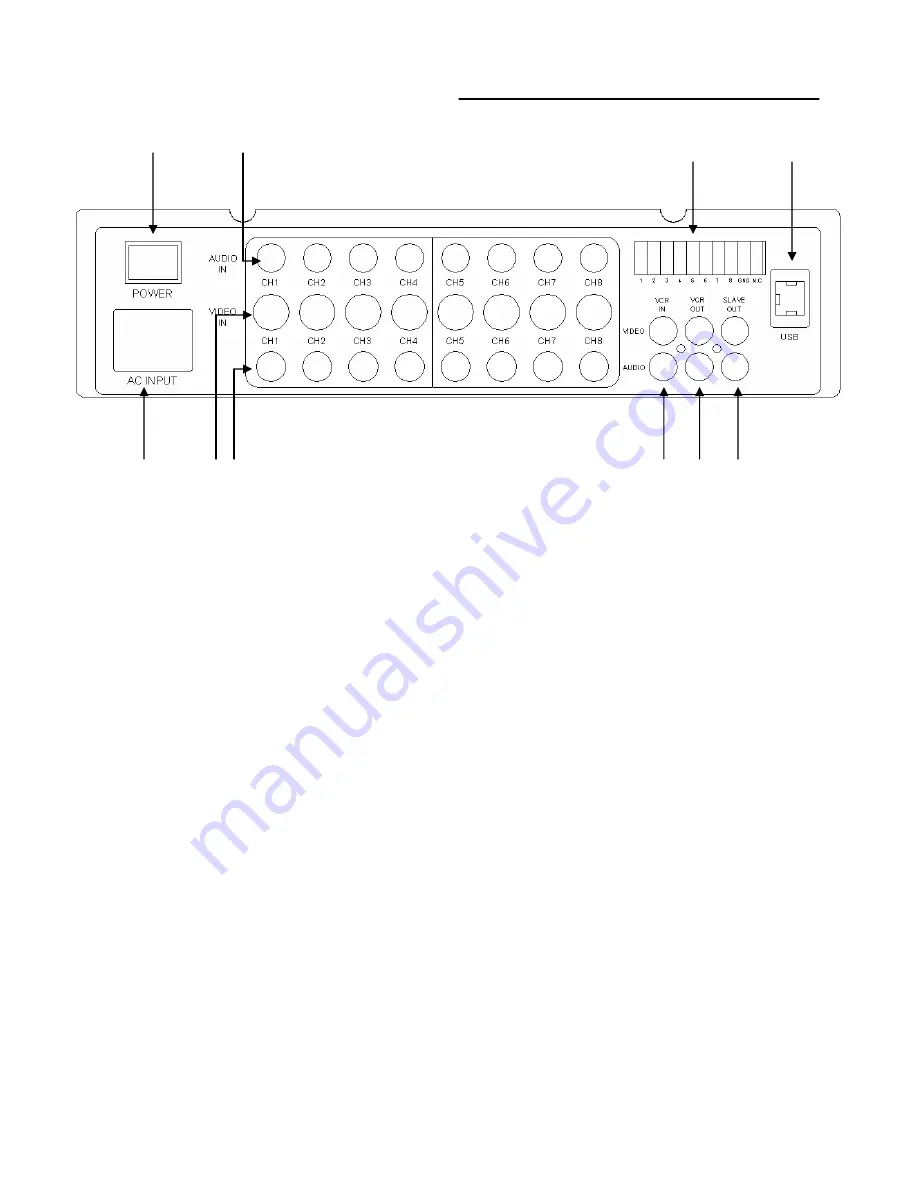
MONITOR CONTROLS - BACK PANEL:

1. Power Switch –

This button controls power to the entire unit. Depress the side with the ”•”

to turn power ON. Depress the other side to turn the unit OFF

2. RCA Audio inputs -

Channel 1-8 Audio inputs.(for cameras with standard RCA Audio output) 

3. Alarm Function Terminals -

These terminals are used to connect external alarm devices 

such as a motion sensor, door/alarm sensor, or time lapse VCR

4. USB Port –

Connects to a PC using a USB cable

5. Slave A/V Out –

Audio/Video Output signal for transmitting to a slave Monitor or VCR

6. VCR Audio/Video Out -

Use the A/V cables (not supplied) to transmit audio and video from

the monitor to a VCR

7. VCR Audio /Video In -

Use with A/V cables (not supplied) to receive audio and video from an 

external source (VCR ) 

8. 6 Pin DIN Camera Inputs -

Channel 1-8 Camera inputs (for cameras with 6 pin DIN inputs) 

9. BNC Camera Inputs -

Channel 1-8 camera inputs (for cameras with standard Video outputs) 

10. AC Input   -

Connects the attached power cord from the monitor to an electrical outlet 

10          9   8                                        

7

6   5  

1                 2                                    

3             

4

Summary of Contents for SY14Q5184UQC-A

Page 1: ...OR QUAD OBSERVATION SYSTEM with INTERNET REMOTE SECURITY MONITORING SY14Q5184UQC A BEFORE OPERATING THIS SYSTEM PLEASE READ THIS MANUAL THOROUGHLY AND RETAIN IT FOR FUTURE REFERENCE FOR MORE INFORMATION WWW STRATEGICVISTA COM ...

Page 2: ...system and to learn about our complete range of accessory products please visit our website at www strategicvista com Explanation of two Symbols The lightning flash with arrowhead symbol within an equilateral triangle is intended to alert the user to the presence of un insulated dangerous voltage within the product s enclosure that may be of sufficient magnitude to constitute a risk of electric sh...

Page 3: ...rovide reasonable protection against harmful interference in a residential installation This equipment generates Uses and can radiate radio frequency energy and if not installed and used in accordance with the instruction may cause harmful interference to radio communications However there is no guarantee that interference will not occur in a particular installation If this equipment does cause ha...

Page 4: ... CAMERA 14 10 MONITOR CONNECTIONS 15 11 TROUBLE SHOOTING 15 12 TECHNICAL SPECIFICATIONS 16 13 OPTIONAL ACCESSORIES 17 14 APPENDIX A CONNECTING MONITOR TO A STANDARD VCR 18 15 APPENDIX B CONNECTING TO A SLAVE MONITOR 19 16 APPENDIX C TYPICAL CONFIGURATION 20 17 APPENDIX D CONNECTING TO A LOREX TIME LAPSE VCR FOR ALARM RECORDING 21 18 APPENDIX E CONNECTING TO A LOREX SINGLE CHANNEL DVR 22 19 CARE AN...

Page 5: ...d of any kind on this product 15 Servicing Do not attempt to service this product yourself as opening or removing covers may expose you to voltage or other hazards Refer all servicing to qualified service personnel 16 Damage Requiring Service Disconnect this product from the power supply and refer servicing to qualified service personnel under the following conditions a When the power supply cord ...

Page 6: ...nd USB Output for Remote Security Monitoring over the Internet software included View up to 8 camera locations in real time Pan Tilt Zoom capable Pelco D Protocol Metal cabinet with 8 camera inputs 8 DIN 8 BNC and 8 audio RCA 2 way audio Single or Dual PIP viewing options main and PIP channels Selectable still frame in quad or full screen Two times zoom Motion Sensing Alarm Function Video loss det...

Page 7: ...n use for observation In standby mode output to a connected time lapse VCR will continue though no picture will be displayed on the monitor s screen TALK STANDBY MUTE POP PIP SEL AUDIO VCR SEQ SUB2 SUB1 P SEQ MENU MIC PAN TILT FRZ ALL VOLUME ALRS CH3 7 CH4 8 CH2 6 CH1 5 QUAD1 2 ENTER MAIN ZOOM Please refer to the Quick Start Guide and on line manual for the Digital Video Monitoring software and fo...

Page 8: ...ons are used to navigate through menu options For more information on Menu mode please refer to page 8 d Scrolls LEFT UP DOWN RIGHT in Zoom mode For more information on Zoom mode refer to page 6 e MOVE ZOOM FOCUS in Pan Tilt mode For more information on Pan Tilt refer to page 10 2 Quad 1 2 Enter This button serves 2 functions a Quad 1 2 Pressing this button goes to Quad viewing mode 2 quad viewing...

Page 9: ...isplay during sequencing To change Sequence settings refer to Page 7 Press SEQ again to escape sequencing mode b Sub1 Used in PIP POP mode Refer to PIP POP explanation on the next page 8 VCR Sub2 This button serves 2 functions a VCR This button will change the display from the camera inputs to the VCR Audio Video playback and recording signal To return to the previous screen press VCR again Note V...

Page 10: ... Please refer to page 8 for more details 10 Audio Select In Quad mode the user can select the channel with audio Pressing this button automatically changes the audio from camera to camera 11 Mute This button mutes audio Press the button again to turn the audio feature back on 12 Talk Press and hold this button to talk to a specific camera location This button must be pressed the entire time while ...

Page 11: ...Change the time 24 hour clock iv DATE Change the date v DATE FORMAT There are three formats to display the date MM DD YYYY for U S A YYYY MM DD for Asian countries DD MM YYYY for European countries 2 Sequence Set This menu allows you to select the time duration for each channel to sequence between cameras You have the option to change the default 3 seconds to a value between 0 59 seconds Note Chan...

Page 12: ...o N C 6 Motion Set This sub menu allows you to enable disable the monitor s Pixel based Motion Sensing feature by dual channels eg Channel 1 Channel 5 Channel 2 Channel 6 MOTION Selecting OFF disables Motion Sensing from triggering any alarm Selecting OSD will allow alarms to be triggered and the letters MD will appear on the screen of the camera location where the alarm is taking place A third op...

Page 13: ... PAN TILT CH1 Activates Pan Tilt mode to become accessible ALARM OUT Select the Alarm Out setting which is defaulted to NO Normally Open DEFAULT SET Selecting Y resets all programmed settings including the date back to the default factory settings 8 Monitor Set Adjust the monitor s Contrast and Brightness You will see this menu on your camera setting rather than on a blue background enabling you t...

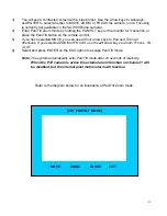
Page 14: ...If you have selected MOVE you can use all four arrow keys to Pan and Tilt in all directions If you selected ZOOM or FOCUS use the arrow keys to Zoom Focus IN OUT 6 Select and press ENTER on the EXIT option to escape Pan Tilt mode Note The system automatically exits Pan Tilt mode after 20 seconds of inactivity When the PTZ camera is active the external alarm function on channel 1 will be disabled b...

Page 15: ...Port Connects to a PC using a USB cable 5 Slave A V Out Audio Video Output signal for transmitting to a slave Monitor or VCR 6 VCR Audio Video Out Use the A V cables not supplied to transmit audio and video from the monitor to a VCR 7 VCR Audio Video In Use with A V cables not supplied to receive audio and video from an external source VCR 8 6 Pin DIN Camera Inputs Channel 1 8 Camera inputs for ca...

Page 16: ...s the Audio channel in Quad mode AUDIO SEL Cuts off the sound from the camera MUTE UP DOWN arrow keys used in Menu mode Displays either PIP POP screen PIP POP Displays Quad screen QUAD 1 2 Initiates automatic sequence in PIP mode P SEQ Sets monitor to VCR mode Changes second sub screen in PIP mode VCR SUB2 Initiates automatic channel scan Changes sub screen in PIP mode SEQ SUB1 Sets monitor to Zoo...

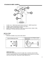
Page 17: ...camera for mounting to walls ceilings or table 5 Microphone Picks up sound around the camera INSTALLATION A Camera Unit Permanent installation using metal camera bracket IMPORTANT NOTE Keep camera installed away from direct sunlight Also avoid places where humidity is high or unable to protect rain The mounting bracket must be attached to a structural device such as wall stud or ceiling rafter usi...

Page 18: ...points TROUBLE SHOOTING VIDEO AUDIO DC12V CAMERA MONITOR PROBLEM REMEDY Too dark or bright picture Readjust the CONTRAST or BRIGHTNESS controls NO POWER Check for AC connection NO POWER Poor picture quality Clean the camera lens Readjust the CONTRAST or BRIGHTNESS controls Picture but no sound Adjust the VOLUME Shrinking picture Check the condition of the POWER source No Picture Picture Flickering...

Page 19: ...D x 12 5 H STANDARD CAMERA Image Device 1 3 CMOS image sensor Resolution 330 TV Lines Shutter control Auto 1 60 1 100 000 Power requirement Powered from monitor via cable Illumination 2 LUX F2 0 Operating Temperature 14 F 122 F 20 C to 50 C Weight 12 oz 340 Grams Dimensions 3 W x 3 6 D x 3 5 H 7 6cm W x 9 1cm D x 8 9cm H Housings White ABS As our products are subject to continuous improvement SVII...

Page 20: ...From a 40 hour real time or 1280 Hour time lapse VCR SPECIALTY CAMERAS Rotates camera up to 270 NIGHTVISION Weatherproof Night vision accessory Allows you to see in the dark up to 35 40 distance SUNSHADE HOUSING Protects observation camera from the sun Select from a wide assortment of specialty cameras dome weatherproof bullet waterproof etc to suit Individual needs AUTO PAN TO ORDER THESE ACCESSO...

Page 21: ...er to ensure reception Consult your VCR s Owners Manual to set the VCR to this setting Important Note To record the video signal from the monitor use the VCR Audio Video out terminals Select the A V or AUX channel on your VCR To record the video out signal included in the On screen display feature e g Date Time Camera identification use the VCR Audio Video Monitor out terminals VCR ...

Page 22: ... 19 APPENDIX B CONNECTING TO A SLAVE MONITOR Connections to another monitor e g Slave Monitor can be made through SLAVE OUT as show in the diagram below MONITOR ...

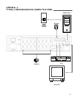
Page 23: ...COMPUTER MONITOR SENSOR VCR APPENDIX C TYPICAL CONFIGURATION FOR COMPLETE SYSTEM USB SIDE PANEL 20 CAMERA ...

Page 24: ...APPENDIX D CONNECTING TO A LOREX TIME LAPSE VCR FOR ALARM RECORDING 21 ...

Page 25: ...r the DVR may indicate a Video Loss as the monitor sequences between channels This Video Loss occurs because the monitor s switching function is analogue whereas the DVR is a digital product Therefore a synchronization problem will result The Solution to this problem is to adjust the Video Loss alarm sensitivity setting to 3 frames on your DVR unit or simply disable the video loss function on your...

Page 26: ...in normal temperature environment Extreme temperatures can shorten the life of the electronic devices Handle the monitor carefully Dropping it can cause serious damage to the unit Occasionally clean the unit with a damp cloth to keep it looking new Do not use harsh chemicals cleaning solvents or strong detergents to clean the unit Keep the unit away from excessive dirt and dust It can cause premat...

Reviews: