Stratasys Origin One User Manual Download Page 18

Basic Setup

Connecting the Power Cable

Page 11

© Copyright 2022 Stratasys. All rights reserved.

Connecting the Power Cable

1. Remove the power cable from the Tools and Cables Accessory Box.
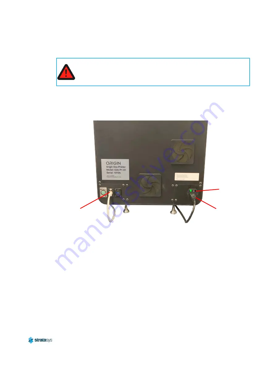
2. Plug the receptacle end of the power cable into the rear of the printer and the three-prong 

(US) or two-prong (EU) end into a grounded outlet. See 

Figure 3

.

Figure 3: Rear Connections

Warning: Electrical Shock Hazard.

A licensed electrician must perform all wiring from the service connection to the 

system - including all connectors, cables, and proper strain relief.
Comply with all applicable local and national electric codes. 

Ethernet Network 

Connection (RJ45)

Power 

Cable 

Connection

Power 

Switch

Summary of Contents for Origin One

Page 1: ...DOC 30001 Rev B Origin One 3D Printing System Version 2 7 User Guide...

Page 2: ...with the furnishing performance or use of this material Stratasys makes no warranty of any kind with regard to this material including but not limited to the implied warranties of merchantability and...

Page 3: ...ou are consuming a translated version please check the English version for latest revision and list of updates Revision Release Date Description of Changes A FEB 2022 Initial Release B MAR 2022 Delete...

Page 4: ...l Safety Hazard Areas 6 Build Chamber 6 Z Stage 6 Door Locks 6 General Safety Practices 6 Environmental Requirements 7 General 7 Physical 7 Environmental 7 2 Printer Setup 8 General Information 8 Welc...

Page 5: ...21 Overview 21 Firewall Configuration 22 Additional Configuration 22 5 Operating the Printer 25 Basic User Operations 25 Powering ON the Printer 25 Pre Print Procedures 27 Installing the Build Head 2...

Page 6: ...ay Sheets 56 Part Replacement Procedures 66 Replacing the Resin Ingress Tube 66 7 Troubleshooting 69 Getting Help 69 Finding a Remedy 70 Troubleshooting Issues and Solutions 71 Stuck Build Head Mitiga...

Page 7: ...ments U S A 78 Canada Electromagnetic compatibility EMC 79 Normes de S curit Canada 79 DOC Statement Canada 79 MSDS Material Safety Data Sheet 79 Disposal of Waste Equipment by Users in Private Househ...

Page 8: ...The following basic safety tips are given to ensure safe installation operation and maintenance of Stratasys equipment and are not to be considered as comprehensive on matters of safety The Origin On...

Page 9: ...refer to the appropriate Safety Data Sheets for additional safety precautions and required PPE Hazard Types Stratasys recommends that all services be performed by qualified personnel All personnel wo...

Page 10: ...other instances and items for which a standard symbol does not exist WARNING Pinch Point This icon identifies instances where moving parts of the machine create a hazard for hands and fingers while t...

Page 11: ...uct Safety Label Locations Figure 1 Front door safety label locations WARNING Do Not Open Opening the door while the machine is in operation will introduce additional hazards To reduce the overall haz...

Page 12: ...Safety Instructions Product Safety Label Locations Page 5 Copyright 2022 Stratasys All rights reserved Figure 2 Linear drive safety label location...

Page 13: ...door open Use caution when accessing the build chamber General Safety Practices Abide by these general safety practices when working with this printer Warning Hot Surfaces Always wear safety gloves a...

Page 14: ...and design dependent Process Energy UV 385nm and Thermal Resin Tray Capacity 15 65 fl oz 2 liters max Supported File Types STL and Zip of PNG images Physical System Dimensions W x D x H Printer Crate...

Page 15: ...ing grade printer that enables additive mass production of end use parts Programmable Photopolymerization P precisely orchestrates light temperature and other conditions automatically optimizing print...

Page 16: ...del will be attached and anchored during the build process 3 Tubing 570mm tube for pump tubing replacement See Chapter 6 Maintenance page 51 4 Fan Filters 4x Replacement fan filters See Chapter 6 Main...

Page 17: ...2 Nameplate Location Making the Network Connection Files can be transfered from App Origin a cloud based application to the Origin One printer through your facility s Ethernet network An RJ45 network...

Page 18: ...he rear of the printer and the three prong US or two prong EU end into a grounded outlet See Figure 3 Figure 3 Rear Connections Warning Electrical Shock Hazard A licensed electrician must perform all...

Page 19: ...nd tips that can be used by the printer is also included in this chapter Printer Overview Main Components This printer has been designed to allow easy access to the most frequently accessed areas on t...

Page 20: ...sys recommends Google Chrome and navigate to https app origin io If Google or Microsoft Azure SSO is supported log in with that account by clicking on Sign in with Google or Sign in with Microsoft Oth...

Page 21: ...s Access to one Netfabb Premium license is granted FOC with each printer purchase Once a part or pack of parts is prepared it can be exported as an STL and uploaded to App Origin to process and print...

Page 22: ...he home screen The home screen displays several buttons sensor readings and shows the progress of a print If the strike bars are installed on the door press Open Door to release the door locks so that...

Page 23: ...icon will appear next to the print until it is ready Press on any file to view a thumbnail and specifications of the print When the printer is prepared and ready to print a file press the Start icon...

Page 24: ...libration see Section 7 1 Project Light Engine Two buttons can be selected here Project Full Area and Project Test Pattern Tapping Project Full Area will cause the projector to illuminate its maximum...

Page 25: ...reads from the glass Interface Resin IR Camera The Interface and Resin IR Camera buttons display a thermal image of the glass or resin tray respectively Print layers can be viewed here in real time as...

Page 26: ...Overview Viewing Print Job Information Page 19 Copyright 2022 Stratasys All rights reserved Viewing Print Job Information Figure 5 Print Job Information Panel...

Page 27: ...Overview Print Status Display Page 20 Copyright 2022 Stratasys All rights reserved Print Status Display Idle Figure 6 Print Status Display Idle...

Page 28: ...commends connecting printers to the Origin cloud platform via VPN because it is secure and robust simple to configure and has zero maintenance overhead With this method all communication is protected...

Page 29: ...Origin printers use DHCP by default but may be configured to static IP addresses on the subnet of your choice The printers use 10 144 0 0 16 internally for VPN communication DHCP must not assign addre...

Page 30: ...ll rights reserved 1 To configure a static IP address navigate to the Network tab on the printer UI and select Static IP Figure 8 Select Static IP 2 After selecting Static IP enter the Static IP addre...

Page 31: ...s reserved 3 Press Confirm after entering each bit segment of the address Figure 10 Press Confirm 4 Once the static IP information is entered select Activate to enable the new network configuration Th...

Page 32: ...nd Ethernet cables are connected See Making the Network Connection page 10 and Connecting the Power Cable page 11 2 Position the power switch to ON Figure 1 Power Button Location and Rear Connections...

Page 33: ...gged into an active port and that the network and firewall are properly configured 5 Contact Stratasys support if network issues persist or if the screen displays any other message Figure 2 Boot scree...

Page 34: ...tasys All rights reserved Pre Print Procedures Installing the Build Head 1 While lifting the thumbscrew slide the build head into the build arm Figure 4 Install build head Warning Crushing hazard Keep...

Page 35: ...en build heads Build head is determined to be no longer in calibration i e first layer inconsistency or failure 1 Ensure that there is no tray installed in the printer The build head will be calibrate...

Page 36: ...ved 3 Navigate to the System tab on the printer UI and select Calibration Procedure Follow the prompts in the video demonstration to complete the calibration procedure Figure 6 Select Calibration Proc...

Page 37: ...ratasys All rights reserved 5 Loosen the calibration bolt with the 10 Nm torque driver until the build head moves freely Figure 8 Loosen calibration bolt 6 Press start calibration The calibration proc...

Page 38: ...Basic User Operations Pre Print Procedures Page 31 Copyright 2022 Stratasys All rights reserved Figure 9 Wait one moment Warning Pinch point Keep hands clear...

Page 39: ...rocedures Page 32 Copyright 2022 Stratasys All rights reserved 7 Once the build head reaches the calibration position adjust the build head so that it s flush and square with the glass interface Figur...

Page 40: ...while using the other hand to tighten the calibration bolt with the 10 Nm torque driver While tightening the calibration bolt ensure that the build head surface remains in close even contact with the...

Page 41: ...ations Pre Print Procedures Page 34 Copyright 2022 Stratasys All rights reserved 10 Press Confirm to complete the build head calibration procedure Figure 13 Calibration complete Warning Pinch point Ke...

Page 42: ...container when finished pouring and return to its storage area 3 Lift the tray using the provided handles and install it in the print chamber Take extra care to avoid contact with the inner walls of...

Page 43: ...y does not move or rock Figure 15 Position tray Web App Usage Uploading Models 1 Access the Origin platform http app origin io login 2 Sign in with your Google account or email Before uploading to App...

Page 44: ...ng Jobs to the Printer 1 After uploading is completed click the thumbnail to select your model for printing 2 After selecting the model thumbnail the model information displays and the print option is...

Page 45: ...ic User Operations Sending Jobs to the Printer Page 38 Copyright 2022 Stratasys All rights reserved be used to estimate resin usage beyond the minimum of 250ml Figure 17 Submit for printing Note 1cm3...

Page 46: ...ld head moves through a cycle of three main stages approach exposure and separation There are eight user defined settings that adjust either the duration distance or speed of some part of the print pr...

Page 47: ...d moves upward this amount to separate the part from the tray window Advancement Delay After the build head has completed its separation it waits this amount of time at the top of travel before advanc...

Page 48: ...All rights reserved After the printer and material options have been selected the Submit option is available Figure 20 Submit part Select Submit to send the file to the printer At the printer select...

Page 49: ...thumbscrew until the build head can be removed from the printer Figure 21 Remove build head WARNING Physical injury Keep one hand on build head when thumbscrew is not completely engaged to avoid drop...

Page 50: ...g area Figure 22 Build head with parts Detaching Printed Parts 1 Using a razor blade or small scraper firmly and carefully scrape along the face of the build head to remove the printed part s Increase...

Page 51: ...tratasys All rights reserved head Hold the build head firmly while keeping fingers and hand clear of the build surface Figure 23 Remove part from build head 2 Remove attached support structures and pl...

Page 52: ...most resins but this will vary based on part geometry and resin type After the parts have been soaked in BATH 3 wipe clean and let air dry or blast with compressed air to clean deep crevices Be sure...

Page 53: ...V curing machine The part may need to be rotated during the cure process to ensure all sides are fully cured A radiometer should be used to ensure the part is receiving a full dosage according to the...

Page 54: ...y tap Release Tray on the touchscreen This will disable the magnets for 5 seconds 2 Gently remove the tray with uncured resin from the printer and carry over to the cleaning area 3 Using a 190 m paint...

Page 55: ...d Cleaning Resin Tray and Build Head 1 Spray IPA over the build head and tray and wipe clean with delicate wipes or paper towels Figure 28 Clean parts with IPA WARNING Skin contact hazard Prolonged co...

Page 56: ...ights reserved 2 Repeat until all resin has been removed from the build head and print tray Figure 29 Cleaned build head and print tray 3 Any material that comes into contact with uncured resin suppor...

Page 57: ...ring OFF the Printer To power the printer OFF 1 Ensure that the printer is stopped idle and is not building 2 Press the power button located on the rear of the printer see Figure 1 for button location...

Page 58: ...ed maintenance Cleaning Cleaning the Mid Plate Glass Window Frequency Check before every print Required Tools Nitrile gloves Single use lint free wipe Acetone Procedure 1 Fold a single use lint free w...

Page 59: ...ntact with resin should be cleaned with IPA after each print job The interior and exterior of the printer may be cleaned with IPA as needed Replacing Fan Filters Frequency Check after 1 month repeat a...

Page 60: ...Stratasys All rights reserved Procedure 1 Locate fan filter on the back panel of the printer Figure 1 Fan filter Note The fan filters are held in place by the fan filter cover The fan filter cover is...

Page 61: ...ter cover by disengaging the fan filter cover clips Figure 2 Disengage cover clips 3 Replace the old filter with a new filter from the accessory tools box 4 Prior to installing the replacement filter...

Page 62: ...5 Reinstall the fan filter cover and replacement filter Engage both fan filter cover clips to secure the fan filter cover to the back panel Figure 4 New fan filter Lubricating the Linear Drive Freque...

Page 63: ...rew shaft Using the grease syringe apply grease directly to the ball screw shaft 5 Apply a 1ml bead of linear drive grease every 2 inches along the ball screw shaft 6 Run the build platform calibratio...

Page 64: ...e goloves 4mm hex 4Nm T handle driver Resin tray thumbscrew Procedure 1 Using a 4mm hex 4Nm T handle driver remove 8 screws from the bottom of the tray Figure 6 Tray and tools Warning Skin contact haz...

Page 65: ...heets Page 58 Copyright 2022 Stratasys All rights reserved 2 Remove the tray bottom by inserting the thumbscrew into the threaded hole on either side of the tray and lifting the tray bottom out of the...

Page 66: ...Remove tray gaskets and tray sheets 4 Dispose of the used tray sheet in a hazardous waste receptacle 5 Retain the tray gaskets for cleaning 6 Use clean paper towels and solvent acetone or isopropyl a...

Page 67: ...residue from the tray threads with compressed air or paper towels Figure 9 Clean tray components 8 Remove any remaining resin from gaskets using paper towels and IPA If needed sonicate the gaskets in...

Page 68: ...air compressor or paper towels Ensure that the gaskets are wiped clean before setting aside to dry Figure 10 Cleaned Gaskets 10 After thoroughly drying insert a clean gasket into the tray top Ensure t...

Page 69: ...ng Tray Sheets Page 62 Copyright 2022 Stratasys All rights reserved 11 Insert a new tray sheet over the gasket and into the tray top Confirm that all the pins are inserted through the holes in the she...

Page 70: ...irm that all the pins are inserted through the gasket holes and that the gasket is laying flat over the tray sheet surface Figure 13 Second gasket 13 Place the tray bottom onto the sheet and press dow...

Page 71: ...y Sheets Page 64 Copyright 2022 Stratasys All rights reserved 14 Remove the thumbscrew from the tray bottom Figure 14 Tray on sheet 15 Insert the 8 tray bolts into the tray bottom Figure 15 Tray bolts...

Page 72: ...s 17 Tighten the tray bolts using the same star pattern shown above by holding the torque driver shaft with the index finger middle finger and thumb Tighten the bolts until they are finger tight Figur...

Page 73: ...or and remove the resin tray if installed 2 With the door open power down and unplug the printer 3 Using a T10 Torx driver remove the two fasteners securing the access panel on the left side of the pr...

Page 74: ...ngress Tube Page 67 Copyright 2022 Stratasys All rights reserved 7 Locate the resin ingress tube The resin ingress tube is surrounded by an orange grommet where it passes through the pump plate See Fi...

Page 75: ...ean any remaining resin on the connectors 14 Remove the replacement resin ingress tube from the accessory tool kit 15 Route the replacement resin ingress tube through the orange grommet 16 Connect one...

Page 76: ...act customer support If needed you can write to Customer Support North America at Stratasys Inc Customer Support 7665 Commerce Way Eden Prairie MN 55344 USA Before calling for service or supplies alwa...

Page 77: ...adiance is fine Increase exposure duration Parts aren t sticking to the build platform Increase exposure delay for the first layer and or increase exposure duration for the first layer Recalibrate the...

Page 78: ...igation Procedure The following is the step by step procedure for mitigation when a build head is stuck in the resin tray and unable to home Procedure 1 Contact Stratasys Customer Support to enable th...

Page 79: ...tize the tray 11 If the build head does not home repeat the procedure 12 Contact Stratasys Customer Support to disable the printer s Dev Mode Solutions for First Layer Adhesion Issues Issue The part f...

Page 80: ...ibed in Build Head Calibration page 28 4 Separation forces are too high Three major factors play into separation forces the viscosity of the resin the stickiness of the resin in its green state and th...

Page 81: ...ay time 3 Separation forces are too high Three important factors in separation force are the viscosity of the resin the stickiness of the resin in the green state and the proximity of the part or buil...

Page 82: ...askets and replace the teflon membrane according to the procedure described in Replacing Tray Sheets page 56 3 Layer shifts due to unwanted build head movement The build head and build arm must remain...

Page 83: ...on to ensure adhesion to the previous layer Solution increase model region projector exposure duration 2 Insufficient model region projector exposure delay time Projector exposure delay times affect t...

Page 84: ...result in part failures When the size of the solid pieces exceeds the build job layer height which is generally the case as we default to 100um layers the pieces can become wedged between the interfa...

Page 85: ...Class A digital device It also conforms to various EU directives including Machinery Directive 2006 42 EC Electromagnetic Compatibility Directive 2014 30 EU and RoHS Directive 2015 863 EU Please refer...

Page 86: ...tions of the Canadian Department of Communications MSDS Material Safety Data Sheet You can obtain current Material Safety Data Sheets for printer materials from the Stratasys website at http www strat...

Page 87: ...responsibility to dispose of your waste equipment by handing it over to a designated collection point for the recycling of waste electrical and electronic equipment The separate collection and recycl...

Page 88: ...info stratasys com STRATASYS COM Copyright 2022 Stratasys Inc All rights reserved...

Reviews: