background image

ii

StorCase Technology, Inc.

DE100i-A100 User's Guide - Rev.

LIMITED WARRANTY

STORCASE TECHNOLOGY, Incorporated (“StorCase”) warrants that its products will be free

from defects in material and workmanship, subject to the conditions and limitations set forth

below.  StorCase will, at its option, either repair or replace any part of its product that proves

defective  by  reason  of  improper  workmanship  or  materials.    Repair  parts  or  replacement

products  will  be  provided  by  StorCase  on  an  exchange  basis,  and  will  be  either  new  or

reconditioned to be functionally equivalent to new.

This warranty does not cover any product damage that results from accident, abuse, misuse,

natural or personal disaster, external power surge or failure, or any unauthorized disassem-

bly, repair or modification. StorCase will not be responsible for any software, firmware or other

customer  data  stored  within,  or  interfacing  with  a  StorCase  product.

Duration  of  Warranty

Seven-Year Warranty:

 The following StorCase products are covered by this warranty for a

period of seven (7) years from the original date of purchase from StorCase or its authorized

resellers: all Data Express® removable device enclosures and all Data Silo®, Data Stacker® and

InfoStation®  external  expansion  chassis,  except  for  those  components  integrated  into  or

purchased separately for use with these products which are identified and covered by the three-

year  or  hard  drive  warranties  described  below.  All  StorCase  interface  cables  and  other

accessories specifically intended for use with the StorCase products identified above are also

covered  by  this  (7)  year  warranty.

Three-Year Warranty

: The following components integrated into or purchased separately for

use with StorCase Data Express, Data Silo, Data Stacker and/or InfoStation products are subject

to warranty for a period of three (3) years from the original date of purchase from StorCase or

its authorized resellers: all RAID controllers, power supplies, fans and blowers.

Two-Year  Warranty

:  The  following  StorCase  products  are  covered  by  this  warranty  for  a

period  of  two  (2)  years  from  the  original  date  of  purchase  from  StorCase  or  its  authorized

resellers: all Rhino®

JR

 fixed external expansion chassis (model types “FJR”) and all Rhino

JR

removable device enclosures (model types “RJR”).

One-Year Warranty

: All StorCase products identified as Reconditioned or “Special Inventory”

are covered by this warranty for a period of one (1) year from the original date of purchase from

StorCase  or  its  authorized  resellers.  Reconditioned  products  may  only  be  exchanged  for

reconditioned  products.

Hard  Disk  Drive  Warranty

:  All  hard  disk  drives  purchased  from  StorCase  or  through  its

authorized resellers, whether purchased separately or integrated into StorCase products, are

subject to the warranty terms and conditions provided by the drive manufacturer.

Third Party Software Warranty

: All third party software purchased from StorCase for use

with  and/or  as  part  of  StorCase  products  is  subject  to  the  warranty  terms  and  conditions

provided  by  the  software  manufacturer.

Summary of Contents for Data Express DE100i-A100

Page 1: ...StorCase Technology Data Express DE100i A100 Removable Ultra ATA133 Drive Enclosure User sGuide...

Page 2: ...gy Inc StorCase Technology Data Express DE100i A100 Removable Ultra ATA133 Drive Enclosure User sGuide Part No D89 0000 0103 C02 October 2005 StorCase Technology Inc 17600 Newhope Street Fountain Vall...

Page 3: ...scribed below All StorCase interface cables and other accessories specifically intended for use with the StorCase products identified above are also covered by this 7 year warranty Three Year Warranty...

Page 4: ...prior to servicing your system This warranty covers only repair or replacement of defective StorCase products as described above StorCase is not liable for and does not cover under warranty any costs...

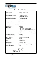
Page 5: ...61000 4 3 EN 61000 4 6 EN 61000 4 4 En 61000 4 8 EN 61000 4 11 EN 60950 CAN CSA C22 2 No 950 95 UL 1950 EN 60950 2000 FCC Part 15 Class B AS NZS 3548 Information Technology Equipment 2000 Company Nam...

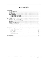
Page 6: ...ATION 7 Installing the Drive into the Carrier 7 Drive Activity Indicator Connector J5 7 Installation 8 Installing the Receiving Frame 9 Selecting the Unit ID Number 10 Unit ID Select Switch Settings 1...

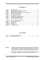
Page 7: ...i A100 Physical Dimensions 16 Figure B 1 Attaching the ON OFF Key 17 Figure C 1 Carrying Case 18 Figure C 2 Full Drive Cover 19 Figure C 3 Drive Plug 19 Figure C 4 Solenoid Mechanism 20 List of Tables...

Page 8: ...ed please call your reseller or StorCase at 800 435 0642 to arrange for a Return Material Authorization RMA StorCase cannot ac cept returns which do not display an RMA number on the outside of the pac...

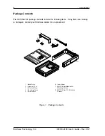
Page 9: ...kage Contents 0430e Data Express Dri ve Ca rrie r Dis k Dri ve No t Inc lud ed Pow er Ca ble I O Ca ble Dri ve Mo unt ing Ha rdw are 4e a Phi llips 6 3 2 x 3 1 6 Fla t HD ID Sel ect Ca ble 0151 Ca ble...

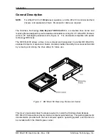
Page 10: ...igure 2 It is downward compatible with earlier technology IDE drives The DE100i A100 allows a drive to be removed and transported to another DE100i A100 equipped computer or expansion chassis and also...

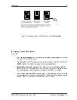
Page 11: ...ber Display Figure 4 shows the physical address of the DE100i A100 drive carrier when the carrier is Installed and Locked in the receiving frame or Removed from the receiving frame If the drive carrie...

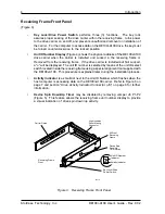
Page 12: ...age 13 for J2 pin assignments Master Slave Selection Jumper J5 Master Drive configuration default Forces master drive configuration on receiving frame Change jumper to set slave drive configuration Re...

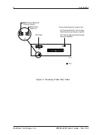
Page 13: ...StorCase Technology Inc DE100i A100 User s Guide Rev C02 6 Introduction Figure 5 Receiving Frame Rear Panel...

Page 14: ...er Slave Drive Selection In most cases the drive will be factory configured as a Master Ultra ATA133 drive using a jumper plug on the drive itself No con figuration changes are required For multiple d...

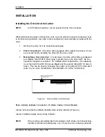
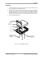
Page 15: ...on process 2 Attach the power cable on the drive carrier circuit board to the drive Carefully insert the drive into the drive carrier at an angle cable end first Make sure none of the cables are pinch...

Page 16: ...nly The master slave setting on must still be set on the drive itself refer to the drive manufacturer s documentation for further information 0423A Slave Drive Select Master Drive Select Factory Defau...

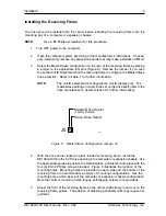
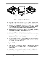
Page 17: ...ripheral cables removed earlier 10 Turn ON power to the computer If the installation has been successful and all the cables have been properly attached the system should boot normally Although the com...

Page 18: ...eceiving frame Table 2 lists the valid unit ID numbers available for the drive 4 After you have selected an appropriate unit number replace the DE100i A100 carrier in the receiving frame and LOCK IT I...

Page 19: ...in the receiving frame display window Table 1 Unit ID Select Switch Settings NOTE The unit ID number display is for ID display purposes only The master slave setting must still be set on the drive it...

Page 20: ...12 I O 13 Host Data 2 I O 14 Host Data 13 I O 15 Host Data 1 I O 16 Host Data 14 I O 17 Host Data 0 I O 18 Host Data 15 I O 19 Ground 20 Key NoPin 21 DMARQ O 22 Ground 23 DIOW O 24 Ground 25 DIOR O 26...

Page 21: ...StorCase Technology Inc DE100i A100 User s Guide Rev C02 14 Appendix A Specifications Dimensions APPENDICES...

Page 22: ...pecifications Operating Storage Ambient Temperature 5 C to 50 C 45 C to 75 C Relative Humidity 1 10 to 80 10 to 90 Altitude 1000 to 50 000 ft 1000 to 50 000 ft 304m to 15240m 304m to 15240m Shock 2 10...

Page 23: ...StorCase Technology Inc DE100i A100 User s Guide Rev C02 16 Appendix A Specifications Dimensions Figure A 1 DE100i A100 Physical Dimensions Dimensions are for reference only...

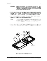
Page 24: ...to the receiving frame Locate the rectangular shaped key lock mecha nism access hole on the inside of the receiving frame Note that the pawl is in an upright position Insert the key into the lock 2 R...

Page 25: ...ansport the DE100i A100 carrier from one site to another in a safe impact and moisture resistant environment Its compact dimensions 7 long x 9 wide x 3 5 high make it easy to carry and to store The fo...

Page 26: ...P N DX100 PLUG is designed to fill system or external enclosure bays that are occupied by receiving frames that have no carrier units installed The purpose of the plug is to provide an attractive and...

Page 27: ...For disk drives this period of time can range from 15 40 seconds depending on the type of drive being used e g Barracuda drives require up to 50 seconds Refer to the drive manufacturer s documentation...

Page 28: ...ion instructions Everyone at StorCase Technology is working toward the goal of providing you with the highest quality most cost effective products available on the market and we need your comments to...

Page 29: ...NG THIS LINE FROM BOTTOM TO TOP OF PAGE BUSINESS REPLY MAIL POSTAGE WILL BE PAID BY ADDRESSEE NO POSTAGE NECESSARY IF MAILED IN THE UNITED STATES FIRST CLASS MAIL PERMIT NO 10686 SANTA ANA CA TECHNOLO...

Reviews: