background image

6


Safety Precautions

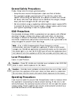
General Safety Precautions

Follow these rules to ensure general safety:

• Keep the area around the appliance clean and free of clutter.
• The appliance weighs approximately 27 kg (60 lbs.) when fully 

loaded. When lifting the appliance, two people at either end should 

lift slowly with their feet spread out to distribute the weight. Always 

keep your back straight and lift with your legs.

• We recommend using a regulating uninterruptible power supply (UPS) 

to protect the device from power surges, voltage spikes and to keep 

your system operating in case of a power failure.

ESD Precautions

Electrostatic discharge (ESD) is generated by two objects with different 

electrical charges coming into contact with each other. An electrical 

discharge is created to neutralize this difference, which can damage 

electronic components and printed circuit boards. Use a grounded wrist 

strap designed to prevent static discharge.

Laser Precautions

Class 1 Laser Product.

Operating Precautions

Care must be taken to assure that the appliance cover is in place when 

the appliance is operating to ensure proper cooling. If this rule is not 

strictly followed, the warranty may become void. Do not open the power 

supply casing. Power supplies can only be accessed and serviced by a 

qualified technician of the manufacturer.

Note – 

Use a UPS (Uninterruptible Power Supply) in critical 

environments with your StoneGate appliance. If after a brief power 

outage your StoneGate appliance only partially starts up (for example, 

the power light is on, but the NIC LEDs are off and the appliance does 

not connect) turn the appliance off for five seconds and then back on.

Caution – 

Class 3B visible and invisible laser radiation when CD-ROM 

drive is open. Avoid exposure to the beam.

Caution – 

Invisible laser radiation emitted from the end of fiber cable 

and from the aperture of the port when no fiber cable is connected. 

Do not stare into the beam and avoid direct exposure to the beam.

Summary of Contents for StoneGate FW-5000 Series

Page 1: ...Appliance Installation Guide FW 5000 Series...

Page 2: ...scribed in these materials are provided pursuant to the general terms for support and maintenance services and the related service description which can be found at the Stonesoft website www stonesoft...

Page 3: ...o the acceptance of the End User License Agreement which can be found at the Stonesoft website Contents Installation Procedure 4 Product Documentation 4 Safety Precautions 5 Unpacking the Appliance 7...

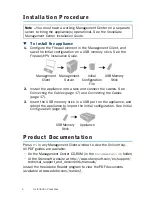
Page 4: ...n See Initial Configuration page 19 Product Documentation Press F1 in any Management Client window to view the Online Help All PDF guides are available On the Management Center CD ROM in the Documenta...

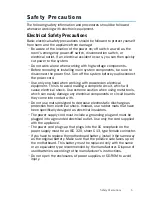
Page 5: ...ich will cause electrical shock Use extreme caution when using metal tools which can easily damage any electrical components or circuit boards they come into contact with Do not use mats designed to d...

Page 6: ...st strap designed to prevent static discharge Laser Precautions Class 1 Laser Product Operating Precautions Care must be taken to assure that the appliance cover is in place when the appliance is oper...

Page 7: ...f it was damaged in any way If the device itself shows damage file a damage claim with the carrier who delivered it Do not remove the anti tamper tapes on any part of the appliance Caution The battery...

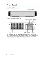
Page 8: ...ard drives a CD ROM drive and two USB ports There are two more USB ports on the back of the appliance See Connecting the Cables page 17 The front panel also has six LED indicators and three buttons wh...

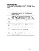
Page 9: ...ctly Indicates an overheat condition in the appliance This may be caused by cables obstructing the airflow in the system or the ambient room temperature being too warm Indicates traffic on the onboard...

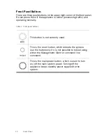
Page 10: ...ng normally Table 2 Front panel buttons This button is not currently used This is the reset button which reboots the system Use the button only if it is not possible to reboot using either the Managem...

Page 11: ...as where heat electrical noise and electromagnetic fields are generated Leave enough clearance in front of the rack to enable you to open the front door completely 63 cm 25 inches Leave enough clearan...

Page 12: ...ts on the devices closed when not servicing to maintain proper cooling Before installing the appliance into a rack Make sure that the rack is securely anchored onto an unmovable surface or structure b...

Page 13: ...the inner rail before installing T To detach the inner rails 1 Pull the inner rail out as far as possible You should hear a click sound as a locking tab emerges from inside the rail assembly and locks...

Page 14: ...inner rails 2 Align the larger end of each hole against its corresponding button Once all are aligned push the holes toward their corresponding buttons 3 Once the rail is placed on the appliance pull...

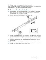
Page 15: ...e The short front brackets are marked with up front arrows and the long rear brackets with up rear arrows 2 Secure the short front bracket to the outer rail 3 Locate the two buttons on the outer rack...

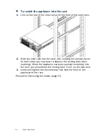
Page 16: ...o the outer rails keeping the pressure even on both sides you may have to depress the locking tabs when inserting When the appliance has been pushed completely into the rack you should hear the lockin...

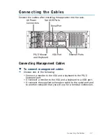
Page 17: ...e one of the following Connect a monitor to the VGA and a keyboard to the PS 2 keyboard port Or connect a monitor to the VGA and a keyboard to a USB port Or connect the supplied null modem cable to th...

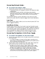
Page 18: ...nd of the cable is set to autonegotiate the other end must also be set to autonegotiate Gigabit standards require interfaces to use autonegotiation fixed settings are not allowed at gigabit speeds Con...

Page 19: ...atically page 20 and you are not interested in the console messages that are displayed during this process In other cases you need a physical connection to the appliance using a monitor and keyboard o...

Page 20: ...l VPN Installation Guide or the Online Help of the Management Client for details If you want to check the configuration before it is activated follow the instructions in Configuring the Engine with Co...

Page 21: ...iguring the Engine with Configuration Wizard T To start the configuration wizard Turn on the appliance using the power on off button The engine bootup process is shown in the console and after some ti...

Page 22: ...using the arrow keys and press ENTER 2 Select the correct timezone in the dialog that opens Note If the desired keyboard layout is not available use the best matching available layout or select US_En...

Page 23: ...on your keyboard to select the option and allow remote access to engine command line using SSH 4 Highlight Next and press ENTER The Configure Network Interfaces window is displayed Note It is not nece...

Page 24: ...how physical interfaces are mapped to the Interface IDs you defined in the Firewall element Ethernet ports are detailed in Connecting the Cables page 17 2 Highlight the Media column and press ENTER t...

Page 25: ...Management Server on this engine using the Management Client T To activate the initial configuration 1 Highlight Switch Firewall Node to Initial Configuration and press spacebar to activate 2 Fill in...

Page 26: ...w tries to make initial Management Server contact If you see a connection refused error message ensure that the one time password is correct and the Management Server IP address is reachable from the...

Page 27: ...d indicating that the Management Server can connect to the node The next step is creating a security policy and installing it on the engine See the Online Help of the Management Client for detailed in...

Page 28: ...plug all power cords from the system or the wall outlets 3 Disconnect all the cables and label the cables for easy identification 4 Use a grounded wrist strap designed to prevent static discharge when...

Page 29: ...remove the drive tray from the appliance T To install a hard drive 1 Press the release tab located on the drive tray door to release the drive tray from its locking position 2 Pull the drive tray doo...

Page 30: ...nal If you want to check the hard disk status type sg raid status on the engine command line 6 Configure the hard disk using one of the following commands and options on the engine command line To add...

Page 31: ...to release the power supply from its locking position 3 Remove the power supply module from the appliance and replace with a new one Caution Unplug the power cord from the power supply module before...

Page 32: ...replacing appliance fans you must first open the appliance s top cover T To replace appliance fans 1 Press the release tabs to release the cover from its locking position 2 Push the cover toward the...

Page 33: ...o release the fan from its locking position 4 Remove the fan from the appliance and replace with a new one Note It is recommended that you replace all the appliance fans at the same time If one of the...

Page 34: ...minal with settings 9600bps 8 databits 1 stopbit no parity 3 Re start the appliance If the appliance is powered on press Enter log in as the user root with the password you have set for the appliance...

Page 35: ...Restore Options from the boot menu 6 Type 1 and press Enter to clear the settings A confirmation prompt is shown 7 Type YES and press Enter to perform the reset If you decide to cancel the operation...

Page 36: ...s on FW 5000 Mother board Slot 6 Slot 5 Slot 4 Slot 3 Slot 2 Slot 1 Eth 10 Eth 14 Eth 18 Eth 6 Eth 0 Eth 11 Eth 15 Eth 19 Eth 7 Eth 1 Eth 12 Eth 16 Eth 20 Eth 8 Eth 2 Eth 4 Eth 5 Eth 13 Eth 17 Eth 21...

Page 37: ...ot 1 Eth 6 Eth 10 Eth 14 Eth 7 Eth 11 Eth 15 Eth 4 Eth 0 Eth 8 Eth 12 Eth 16 Eth 5 Eth 1 Eth 2 Eth 3 Eth 9 Eth 13 Eth 17 Table 6 Ports on FW 5000F3 Mother board Slot 6 Slot 5 Slot 4 Slot 3 Slot 2 Slot...

Page 38: ...ot 4 Slot 3 Slot 2 Slot 1 Eth 6 Eth 7 Eth 10 Eth 12 Eth 4 Eth 0 Eth 8 Eth 11 Eth 13 Eth 5 Eth 1 Eth 2 Eth 3 Eth 9 Table 8 Ports on FW 5000L Mother board Slot 6 Slot 5 Slot 4 Slot 3 Slot 2 Slot 1 Eth 2...

Page 39: ...ard Slot 6 Slot 5 Slot 4 Slot 3 Slot 2 Slot 1 Eth 2 Eth 6 Eth 3 Eth 7 Eth 10 Eth 4 Eth 8 Eth 11 Eth 0 Eth 1 Eth 5 Eth 9 Table 10 Ports on FW 5000LF2 Mother board Slot 6 Slot 5 Slot 4 Slot 3 Slot 2 Slo...

Page 40: ...t 3 Slot 2 Slot 1 Eth 6 Eth 10 Eth 14 Eth 2 Eth 7 Eth 11 Eth 15 Eth 3 Eth 8 Eth 12 Eth 16 Eth 4 Eth 0 Eth 1 Eth 9 Eth 13 Eth 17 Eth 5 Table 12 Ports on FW 5100G1 Mother board Slot 6 Slot 5 Slot 4 Slot...

Page 41: ...ot 3 Slot 2 Slot 1 Eth 6 Eth 2 Eth 10 Eth 12 Eth 7 Eth 3 Eth 11 Eth 13 Eth 8 Eth 4 Eth 0 Eth 1 Eth 9 Eth 5 Table 14 Ports on FW 5100F1 Mother board Slot 6 Slot 5 Slot 4 Slot 3 Slot 2 Slot 1 Eth 4 Eth...

Page 42: ...ot 5 Slot 4 Slot 3 Slot 2 Slot 1 Eth 4 Eth 8 Eth 5 Eth 9 Eth 12 Eth 2 Eth 6 Eth 10 Eth 13 Eth 3 Eth 0 Eth 1 Eth 7 Eth 11 Table 16 Ports on FW 5100F3 Mother board Slot 6 Slot 5 Slot 4 Slot 3 Slot 2 Slo...

Page 43: ...Ethernet Port Numbering 43 Table 17 Ports on FW 5100F4 Mother board Slot 6 Slot 5 Slot 4 Slot 3 Slot 2 Slot 1 Eth 4 Eth 6 Eth 8 Eth 2 Eth 5 Eth 7 Eth 9 Eth 3 Eth 0 Eth 1...

Page 44: ...us colors vary between appliance models and NIC types The port LED Indicators for different ports and NICs are presented below Motherboard Ports Table 18 LEDs per Motherboard Ports Indicator Status Ex...

Page 45: ...s 45 Gigabit Copper NIC Table 19 LEDs in Gigabit Copper NIC Indicator Status Explanation LINK ACT Green Link ok Blinks on activity 100 Green Speed is 100 Mbps 1000 Green Speed is 1 Gbps LINK ACT 100 a...

Page 46: ...C Table 20 LEDs in Gigabit Copper NIC Indicator Status Explanation ACT LINK Green Link ok Blinks on activity 10 100 1000 Unlit Speed is 10 Mbps 10 100 1000 Green Speed is 100 Mbps 10 100 1000 Orange S...

Page 47: ...C Table 21 LEDs in Gigabit Copper NIC Indicator Status Explanation ACT LINK Green Link ok Blinks on activity 10 100 1000 Unlit Speed is 10 Mbps 10 100 1000 Green Speed is 100 Mbps 10 100 1000 Yellow S...

Page 48: ...48 Port Indicators Gigabit Fiber NIC Table 22 LEDs in Gigabit Fiber NIC Indicator Status Explanation ACT LNK Lit Link ok Blinks on activity ACT LNK...

Page 49: ...PortIndicators 49 Gigabit Fiber NIC Table 23 Gigabit Fiber NIC Indicator Status Explanation ACT Green Blinks on activity LNK Green Link ok LNK ACT...

Page 50: ...uctions Dispose of the appliance separately from household waste at an appropriate waste disposal facility at the end of its useful service life Table 24 LEDs in 10 Gigabit Fiber NIC Indicator Status...

Page 51: ...documentation See inside for further details All documentation and our technical knowledge base is available at www stonesoft com support Copyright 2010 Stonesoft Corporation Stonesoft Inc Americas He...

Reviews: