Stoelting SU412 Operator'S Manual Download Page 29

Owner’s Manual #513625 

25 

SU412 Model Machines

tension for the drive belt. Set the belt tension to 
15 - 25 lbs.

C. 

If an adjustment is necessary, loosen the four 
motor plate retaining nuts, adjust belt tension 
then retighten the four nuts.

D. 

Using a straightedge, check that the drive motor 
pulley is aligned with the speed reducer pulley. 
Align the pulley if necessary.

NOTE

Belt life will be increased if new drive belts are 
tightened after two or three weeks of operation.

4.13 

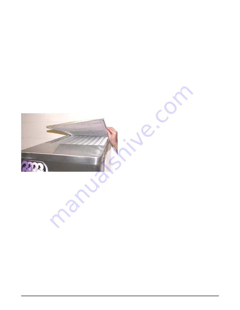
CONDENSER CLEANING (AIR-COOLED 

FREEZERS)

The condenser requires periodic cleaning. To clean the 
condenser, refer to the following steps:

A. 

Lift the condenser fi lter off of the freezer cover 

panel. Visually inspect the condenser fi lter for dirt 
(Fig. 4-4).

B. 

If the condenser fi lter is dirty, vacuum or brush 
it clean. Rinse it with clean water and allow it to 
dry before replacing it on the freezer.

NOTE

If the condenser is not kept clean, refrigeration ef-
fi ciency will be lost.

4.14 PREVENTATIVE 

MAINTENANCE

It is recommended that a preventative maintenance 
schedule be followed to keep the freezer clean and op-
erating properly. The following steps are suggested as a 
preventative maintenance guide.

The United States Department of Agriculture and the Food 

and Drug Administration require that lubricants used in 
food zones be certifi ed for this use. Use lubricants only in 
accordance with the manufacturer’s instructions.

A. Daily 

checks


Check for any unusual noise or condition and 
repair immediately.

B. Monthly 

checks


1. Check drive belts for wear and tighten belts if 
necessary. (Refer to section 4.12)


2. Check the condenser fi lter for dirt. (Refer to 
section 4.13).

4.15 EXTENDED 

STORAGE

Refer to the following steps for winterizing the freezer or 
for storing the freezer over any long period.

A. 

Clean all of the parts that come in contact with 
mix thoroughly with warm detergent . Rinse in 
clear water and dry all parts. Do not sanitize.

NOTE

Do not let cleaning solution stand in freezer barrel 
or mix pump during the shutdown period.

B. 

Remove, disassemble, and clean the front door, 
auger shaft, and mix pump. Leave disassembled 
during the shutdown period.

C. 

Place the plastic scraper blade in a plastic bag 
with a moist paper towel. This will prevent the 
fl ights from becoming brittle if exposed to dry air 
over an extended period (over 30 days).

D. 

For water-cooled freezers that are left in unheated 
buildings, or buildings subject to freezing, the water 
must be shut off and disconnected. Disconnect 
the fi ttings at the water inlet and the water outlet 
lines of the freezer. The fi ttings are located at the 
rear of the freezer. Run the compressor for 2 - 3 
minutes to open the water valve. Blow out all the 
water, fi rst through the water inlet, then through 
the water outlet lines with air or carbon dioxide. 
Drain the water supply line  coming to the freezer.

E. 

Place the Pump OFF/ON switch and the Main 
Freezer Power OFF/ON switch in the OFF 
position.

F. 

Disconnect the freezer from the source of the 
electrical supply in the building.

Figure 4-4 Removing Condenser Filter

Summary of Contents for SU412

Page 1: ...Model SU412 OPERATORS MANUAL Manual No 513625 Rev 4...

Page 2: ......

Page 3: ...built prior to date of change DO NOT ATTEMPT to operate the machine until instructions and safety precautions in this manual are read completely and are thoroughly understood If problems develop or q...

Page 4: ...ecific safety information the following safety defini tions are provided to assist the reader The purpose of safety symbols is to attract your at tention to possible dangers The safety symbols and the...

Page 5: ...ting Controls and Indicators 7 3 3 Emptying the Freezing Cylinder 9 3 4 Disassembly of Machine Parts 9 A Remove Blender 9 B Remove Front Door 10 C Remove Auger 10 D Pump Hose Disassembly 10 3 5 Cleani...

Page 6: ...rrun Adjustment 22 4 9 Mix Pump Hose Reposition 23 4 10 Mix Pump Hose Replacement 23 4 11 Cab Temperature Adjustment 24 4 12 Drive Belt Tension Adjustment 24 4 13 Condenser Cleaning Air Cooled Freezer...

Page 7: ...machine It is equipped with fully automatic controls to provide a uniform product This manual is designed to assistqualifiedservicepersonnelandoperatorswithinstal lation operationandmaintenanceoftheS...

Page 8: ...VAC 60Hz circuit ampacity 19A minimum overcurrent protection device 30A maximum Compressor 11 000 Btu hr Scroll Compressor Drive Motor 3 4 hp Air Flow Air cooled units require 3 7 6 cm air space on b...

Page 9: ...ise the carrier within 10 days and request inspection The customer must place a claim for damages and or short ages in shipment with the carrier Stoelting Inc cannot make any claims against the carrie...

Page 10: ...the left side of the mix line manifold using a small hose clamp Be careful not to twist the mix hose 7 Turn the pump on 8 Allow the remaining 6 15cm of tubing to feed through pump until the hose adap...

Page 11: ...em BCS withThree Bags optional kit The position of the three bags in the mix container is im portant The bag that is connected nearest the outlet of the manifold drains last and should be placed at th...

Page 12: ...f the tubing to a manifold adapter Securewithalargehose clamp 3 Push the manifold adapter with spring and valve into the left port nearest the manifold outlet of the mix inlet manifold and secure with...

Page 13: ...perating control Refer to Figure 3 1 for the location of the operating controls on the machine For the information regarding error codes displayedonthecontrolpanel refertothetroubleshooting section of...

Page 14: ...he freezing cycle stops and the drive motor starts A CLEAN message will display on the LCD screen along with a 5 minute countdown timer If the button is pressed again the timer resets To exit the CLEA...

Page 15: ...ld the blender shaft and turn the agitator counterclockwise b Loosenknobsholdingtheblendersplashshield assembly in place and remove the assembly 3 Remove the knobs on the front door Remove the blender...

Page 16: ...r bleed valve by unscrewing the knob while holding the valve stem from behind Remove the compression spring and push the air bleed valve through the rear of the front door 4 Removethespigotthroughtheb...

Page 17: ...he steel A Clean the rear seal surface at the back of the freezing cylinder B Using sanitizing solution and the large barrel brush provided sanitize the freezing cylinder by dipping the brush in the s...

Page 18: ...with the manufacturer s instructions CAUTION Risk of Product Damage Avoid prolonged contact of sanitizer with machine parts Sanitizer may cause corrosion of stainless steel parts if there is prolonge...

Page 19: ...again will change the value to 0 13 After entering 8 0 press SET to save this value The LCD will read CutOut Set OK 14 Press the SEL button The LCD will read CutOut amps 8 0 15 Press the SEL button t...

Page 20: ...gerated cab E Place the mix pump switch in the ON position F Place a container under the spigot and open the spigot to allow the mix to flush out about 8 ounces 0 23 liters of sanitizing solution and...

Page 21: ...he mix intake or pickup The right sideofthehoseisthemixdischarge Mixisdrawn up the pickup side of the hose and transferred through the discharge side to the machine Fig 3 10 B Air Operation The air co...

Page 22: ...apter and bag adapter if applicable as an assembly from the mix container C Completely disassemble the hose assembly and the check valve Fig 3 11 Place hoses tee checkvalveassembly andpickuphoseadapte...

Page 23: ...use When set all buttons on the control panel are disabled Follow the instructions below to lock the control panel A Press and hold the PUSH TO FREEZE button for at least 5 seconds B While still holdi...

Page 24: ...Suction line temperature on the freezing cylinder and drive motor amps are available on the same screen to assist with setup and troubleshooting Aux Temp F This reading provides the ambient temperatu...

Page 25: ...reat which the freezing cycle starts This value along with the CutOut value determines the range of temperatures or temperature window of the product Decreasing the temperature decreases the temperatu...

Page 26: ...Hopper or 2 Hopper is selected for the Refriger setting Cab Off will not be shown on the IntelliTec menu Cab On If the Refriger value is set to Cabinet and the temperaturesensorinthecabinetfails thiss...

Page 27: ...ollow the steps below to reposition the hose A Run cleaning solution through pump B Turn the pump off and relieve any pressure by opening the spigot C Grasp the pickup hose end of the mix pump hose wi...

Page 28: ...ress and hold SEL button for 8 seconds While still holding the SEL button press the up arrow button The LCD Screen will read Display B Release both buttons C Press the left arrow button three 3 times...

Page 29: ...for any unusual noise or condition and repair immediately B Monthly checks 1 Check drive belts for wear and tighten belts if necessary Refer to section 4 12 2 Check the condenser filter for dirt Refe...

Page 30: ...Owner s Manual 513625 26 SU412 Model Machines...

Page 31: ...r or from product breakdown Another common cause results from a restriction preventing mix fromenteringthefreezingcylinder Checkthemix in the hopper If the level mix is low add mix If there is a possi...

Page 32: ...If the error persists contact your Authorized Stoelting Distributor for further assistance Error Code 9 High Pressure Cutout High Pressure Cutout Errors E9 are usually caused by a dirty or inefficien...

Page 33: ...See Section 3 2 Low overrun setting 2 Raise overrun See Section 4 3 Low pump pressure 3 Check pump pressure 4 Large air pocket in barrel 4 Purge air from barrel 5 Auger turning counter clockwise 5 Ch...

Page 34: ...case turn the pump off Draw 2 3 pints to reduce system pressure to zero Turn pump on Purge remaining air in mix bag and pick up hose Important before connecting the pick up hose to the mix bag remove...

Page 35: ...iately disassemble and clean pump 1 Mix pump hose service life is exceeded 1 Remove mix pump hose Disconnect pump from power source Remove mix pump cover clamp Clean the rollers a small amount of soap...

Page 36: ...Owner s Manual 513625 32 SU412 Model Machines...

Page 37: ...Caution Rotating Blades 1 324200 Decal High Pressure Cut Out 1 324208 Decal Attention Refrigerant Leak Check 1 324346 Decal Caution Hazardous Moving Parts 1 324478 Decal Electrical Box L H 1 324509 D...

Page 38: ...82019 Knob Front Door Black 4 624520 O Ring Air Bleed Valve Black 2 624614 O Ring Spigot Black 2 624678 O Ring Rear Seal Black 2 625314 O Ring Front Door Black 1 667868 Seal Rear Auger Orange 1 694200...

Page 39: ...lender Agitator Collar SU412 1 417010 Grid Drip Tray Metal 1 521026 Blender Agitator SU412 1 674147 Blender Shaft 5 SU412 1 674174 Blender Shaft 7 6 SU412 1 674183 Blender Shaft 6 6 SU412 1 681518 Swi...

Page 40: ...Cone Cab Check Valve 1 696152 Clip Lock Check Valve Cab 3 756067 Tubing 1 4 ID Clear Air Line 25 Increments Per Inch 13 756079 Tubing 3 8 ID Clear Mix Line 25 Increments Per Inch 24 756088 Tubing 1 2...

Page 41: ...se obligations remedies are subject to the conditions that Buyer a signs and returns to Stoelting upon installation the Start Up and Training Checklist for the affected equipment b gives Stoelting pro...

Page 42: ...ed to hoses piping or electrical equipment e Labor and travel charges due to return trips or waiting if the Authorized Stoelting Provider is prevented from promptly starting service work upon arrival...

Reviews: