


Owner’s Manual #513698 Rev.1
9
AUTOVEND Model Machines
A. INSTALLING AUGER
1.
Install the rear seal o-rings. Lubricate the outside
of the rear seal o-rings with a generous amount
Total Blend lubricant.
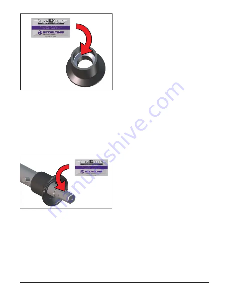
2.
Lubricate the inside metal surfaces of the rear
seals (Fig. 2-18) and install them onto the auger
shaft. DO NOT lubricate the outside of the rear
seals.
3.
Lubricate the hex drive ends of the auger with a
small amount of Total Blend lubricant.
4.
Screw the springs onto the studs in the plastic
fl ights. The springs must be screwed into the
fl ights completely to provide proper compression.
5.
Install the two plastic fl ights onto the rear of the
augers and insert them part way into the freezing
cylinder.
6.
Install the remaining plastic fl ights, push the augers
into the freezing cylinders and rotate slowly until
the augers engage the drive shafts.
7.
Apply a thin layer of sanitary lubricant to the inside
and outside of the auger support bushings. Install
the bushings onto the auger supports and install
the auger supports into the front of the augers.
Rotate the auger supports so that one leg of the
support points straight up.
B. INSTALLING FRONT DOOR
1.
Install the o-rings onto the spigot bodies and apply
a thin layer of sanitary lubricant to the o-rings.
Install the spigot bodies through the bottom of
the front door.
2.
Fit the front door o-rings into the grooves on the
rear of the front door.
3.
Place the front door assembly on the mounting
studs and the push front door against the machine
carefully.
NOTE
Make sure the pins of the front door do not touch
the legs of the auger support.
4.
Secure the front door to the machine by placing
the knobs on the studs and tightening until fi nger
tight. Tighten in a crisscross pattern. Do not
overtighten. Proper o-ring seal can be observed
through the transparent front door.
5.
Install the spigot pins through the actuators and
spigots.
6.
Install the rosette caps to the bottom of the front
door.
C. INSTALLING TOPPING ASSEMBLY
1.
Install the auger assemblies into the topping bins.
Install the agitator into the bin on the far left.
2.
Install the canisters into the brackets. When
installing, tilt the canister backwards to engage
the motor shaft, then press downward to lock into
place.
NOTE
The canister with the agitator must be installed
furthest left.
3.
Install the chutes onto the dispense slides.
4.
Install the chute cones. Make sure the metal lip
of the chute is inside the cone.
2.8 SANITIZING
Sanitizing must be done after the machine is clean and
just before the machine is fi lled with mix. Sanitizing the
night before is not effective. However, you should always
clean the machine and parts after using it.
NOTE
The United States Department of Agriculture and
the Food and Drug Administration require that all
cleaning and sanitizing solutions used with food
processing equipment be certifi ed for this use.
Figure 2-19 Lubricate Auger Spline
Figure 2-18 Lubricate Rear Seal
Summary of Contents for AUTOVEND
Page 1: ...Model AUTOVEND OPERATORS MANUAL Manual No 513698 Rev 1...
Page 2: ......
Page 6: ......
Page 22: ...Owner s Manual 513698 Rev 1 16 AUTOVEND Model Machines...


