background image

Page 22

Due to continuous product research and development,
the information contained herein is subject to change without notice.

www.stoddart.com.au
www.stoddart.co.nz

700/900

3.0 Installation

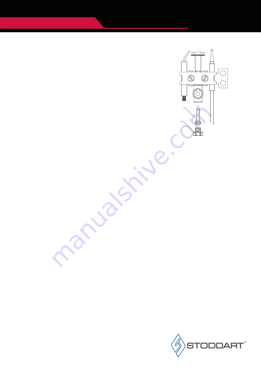
To replace the pilot nozzle:

1.  Close gas isolation valve
2.  Ensure the area is ventilated
3.  Unscrew nut ‘F’ (Fig.8) on the pilot gas tube
4.  Remove the nozzle ‘G’ (Fig.8) and replace it with the one for the type of gas chosen
5.  Re-install the nozzle and nut
6.  Check for gas leak using water and detergent solution

3.4.3 Pilot Nozzle Replacement

3.4.4 Final Check - Main Burner

After replacement of burner nozzles and checking the fixed primary air, light the appliance and check that the ignition and flame are operating 
correctly, with the minimum adjustment set as per page 8 / 2.1.3. If operating incorrectly, repeat the previous steps.

When conversion has been completed for the relevant Gas Type, it is MANDATORY to edit the Rating Plate, with the new Gas Specification.

Once the Gas conversion has been completed, the unit must be leak tested.

Fig.7. 


F

G

Summary of Contents for GIORIK 700 Series

Page 1: ...7207TT FG7417PT FG7817PT Gas FG9207TT FG9421PT FG9821PT Electric FE7110TT FE7117T FE7207T FE7210TT FE7217T Electric FE9121T FE9207T FE9221T 700 Series 900 Series Models 700 900 INSTALLATION OPERATION MAINTENANCE MANUAL READ ALL INSTRUCTIONS BEFORE USE ...

Page 2: ...Page Intentionally Left Blank Page 1 Due to continuous product research and development the information contained herein is subject to change without notice www stoddart com au www stoddart co nz ...

Page 3: ...tion 3 2 Line up Connection 17 3 3 Gas Connection Gas Models 19 3 3 1 Connecting the gas 3 3 2 Gas Pressure Regulator 3 3 3 Gas Pressure Check 3 4 Gas Conversion Internal Burners 21 FG7207TT FG9207TT 3 4 1 Replacing the Main Burner Nozzle 3 4 2 Fixed Primary Air Regulation 3 4 3 Pilot Nozzle Replacement 3 4 4 Final Check Main Burner 3 5 Gas Conversion External Burners FG7417PT FG7817PT FG9421PT FG...

Page 4: ... persons units or others due to abuse and misuse of this unit in regards to installation removal operation servicing or maintenance or lack of conformity with the instructions indicated in this documentation Disclaimer All units made by the manufacturer distributor are delivered assembled where possible and ready to install Any installation removal servicing maintenance and access or removal of an...

Page 5: ...ormation All Stoddart manufactured and distributed products are covered by Stoddart s standard Australia and New Zealand Product Warranty minimum 12 month on site parts and labour terms and conditions apply Further to this standard warranty certain products have access to an extended warranty Full terms conditions and exclusions can be found using the below Link QR code Warranty Registration 1 2 2...

Page 6: ...objects to activate controls If any fault is detected refer to troubleshooting The manufacturer declines any liability for damages to persons and or things due to an improper wrong and or unreasonable use of the machine Only specifically trained qualified Technicians Stoddart one of our service agents or a similarly qualified persons should carry out any and all repairs maintenance and services Wh...

Page 7: ...ble means to move the unit For smaller items use two people For large items a fork lift pallet trolley or similar the forks should reach completely beneath the pallet Check the unit for damage before and after unpacking If unit is damaged contact the distributor and manufacturer Should any item have physical damage report the details to the freight company and to the agent responsible for the disp...

Page 8: ...al Test Gas Pressure 1 3 kPa 2 75 kPa 1 3 kPa 2 75 kPa 1 3 kPa 2 75 kPa Maximum Normal Test Gas Pressure 3 5 kPa 3 5 kPa 3 5 kPa 3 5 kPa 3 5 kPa 3 5 kPa Nominal Test Point Pressure 1 0 kPa 2 65 kPa 1 0 kPa 2 65 kPa 1 0 kPa 2 65 kPa Total Nominal Gas Consumption 43 2 MJ h 43 2 MJ h 57 6 MJ h 57 6 MJ h 115 2 MJ h 115 2 MJ h 900 Series Gas Model FG9207TT FG9421PT FG9821PT Description Gas Fryer Tube S...

Page 9: ...1 Ltr Main burner gas injector 100th of a mm 255 Natural Gas 155 Universal LPG Imported by STODDART www stoddart com au Model No FG7417PT Serial No 009998 06 21 Total gas consumption 57 6 MJ h Test Point Pressure 1 00 kPa Natural Gas 2 65 kPa Universal LPG Factory set gas type Natural Gas Universal LPG Gas Approval No SAI 400414 Description Giorik 700 Fryer Gas Single Pan 17 Ltr V kW HZ Ph 415 14 ...

Page 10: ...0 70 358 700 250 57 A 720 MA X 185 170 16 0 140 C MA X 185 170 16 0 140 C 570 746 800 A 358 70 700 250 57 228 20 380 720 280 700 Series Electric Model FE7110TT Description Electric Fryer Single Pan 10Ltr Counter Top Weight 30kg Overall Height 358mm Overall Depth 720mm Overall Width 400mm Electrical Connection 3Ø N E 415VAC 50Hz 10 8kW 700 Series Electric Model FE7210TT Description Electric Fryer D...

Page 11: ...10 855 900 1039 1084 720 MA X 185 170 16 0 140 C MA X 185 170 16 0 140 C 70 1054 465 700 870 150 292 400 20 380 130 310 A 855 900 1039 1084 720 700 Series Electric Model FE7207T Description Electric Fryer Split Pan 8 8Ltr On Base Weight 62kg Overall Height 1054mm Overall Depth 720mm Overall Width 400mm Electrical Connection 3Ø N E 415VAC 50Hz 15kW 700 Series Electric Model FE7117T Description Elec...

Page 12: ...17T 2 2 6 FG7207TT 2 0 Specification 700 Series Electric Model FE7217T Description Electric Fryer Double Pan 21 21Ltr On Base Weight 90kg Overall Height 1054mm Overall Depth 720mm Overall Width 800mm Electrical Connection 3Ø N E 415VAC 50Hz 35 6kW 700 Series Gas Model FG7207TT Description Gas Fryer Tube Split Pan 8 8Ltr On Base Weight 73kg Overall Height 1054mm Overall Depth 720mm Overall Width 40...

Page 13: ...t 68kg Overall Height 1054mm Overall Depth 720mm Overall Width 400mm Electrical Connection 1Ø N E 240VAC 50Hz 0 2kW 10A plug lead Natural Universal LPG Gas Connection 1 2 BSP 1 2 BSP Minimum Normal Test Gas Pressure 1 3 kPa 2 75 kPa Maximum Normal Test Gas Pressure 3 5 kPa 3 5 kPa Nominal Test Point Pressure 1 0 kPa 2 65 kPa Total Nominal Gas Consumption 57 6 MJ h 57 6 MJ h 700 Series Gas Model FG...

Page 14: ...00 292 400 20 582 310 130 A 855 900 1039 1084 920 Legend A Electrical Connection Legend A Electrical Connection 2 2 9 FE9207T 2 2 10 FE9121T 900 Series Electric Model FE9207T Description Electric Fryer Split Pan 8 8Ltr On Base Weight 88kg Overall Height 1054mm Overall Depth 920mm Overall Width 400mm Electrical Connection 3Ø N E 415VAC 50Hz 15kW 900 Series Electric Model FE9121T Description Electri...

Page 15: ...Connection 2 2 11 FE9221T 2 2 12 FG9207TT 900 Series Gas Model FG9207TT Description Gas Fryer Tube Split Pan 8 8Ltr On Base Weight 88kg Overall Height 1054mm Overall Depth 920mm Overall Width 400mm Electrical Connection 1Ø N E 240VAC 50Hz 0 2kW 10A Plug Lead Natural Universal LPG Gas Connection 1 2 BSP 1 2 BSP Minimum Normal Test Gas Pressure 1 3 kPa 2 75 kPa Maximum Normal Test Gas Pressure 3 5 k...

Page 16: ...8kg Overall Height 1054mm Overall Depth 920mm Overall Width 400mm Electrical Connection 1Ø N E 240VAC 50Hz 0 2kW 10A Plug Lead Natural Universal LPG Gas Connection 1 2 BSP 1 2 BSP Minimum Normal Test Gas Pressure 1 3 kPa 2 75 kPa Maximum Normal Test Gas Pressure 3 5 kPa 3 5 kPa Nominal Test Point Pressure 1 0 kPa 2 65 kPa Total Nominal Gas Consumption 68 4 MJ h 68 4 MJ h 900 Series Gas Model FG982...

Page 17: ...0mm 0mm 0mm Choose an area that is well ventilated and provides access for future maintenance Place the unit on a level stable work surface capable of supporting its weight Unit must be installed on a non combustible floor Unit must be installed on a fire proof base Do not position the unit in wet areas near heat and or steam sources near flammable substances The appliances are not designed for bu...

Page 18: ...ining screws then remove the front fascia by lifting the fascia up and out Using a Phillips head screwdriver remove the rear cover plate and retaining screws On the side of the units to be connected using long nose pliers remove the fill caps 3 2 Line up Connection WARNING Must be installed only by an authorised service person If the unit is already installed and connected to power the power to th...

Page 19: ...ce www stoddart com au www stoddart co nz 700 900 3 0 Installation 5 6 Place the units to be connected next to each other adjust the legs ensuring the top of the two units sit flush Using the provided bolts and nuts connect the units at the front and rear Re install the back cover plate the front fascia and the control dials ...

Page 20: ...ire of adequate strength shall be fixed to the appliance and be suitable to be fixed to the wall within 50 mm of each connection point The length of the chain or wire shall not exceed 80 of the length of the hose assembly The appliance shall be installed by an Authorised Person Installer and in accordance with the manufactures instructions Australian and New Zealand Gas installation standards and ...

Page 21: ...ww stoddart co nz 700 900 3 0 Installation Fig 5 3 3 3 Gas Pressure Check Ensure Burner Gas pressure matches the rating label see page 8 2 3 1 If the gas operating pressure is incorrect adjust pressure regulator installed on the incoming gas supply to the unit The operating pressure is measured at the pressure inlet test point fig 5 Inlet Test Point ...

Page 22: ...on Bushing C Nozzle D Fixed Nozzle Holder Nut E Bushing Lock Screw 3 4 Gas Conversion Internal Burners IMPORTANT Gas Conversion must only be carried out by an authorised person Incorrect installation may void warranty Fig 6 A B C D E The fixed primary air is properly regulated if flame stability is ensured if there are no breaks in the flame with the burner cold and no flashback when the burner is...

Page 23: ...install the nozzle and nut 6 Check for gas leak using water and detergent solution 3 4 3 Pilot Nozzle Replacement 3 4 4 Final Check Main Burner After replacement of burner nozzles and checking the fixed primary air light the appliance and check that the ignition and flame are operating correctly with the minimum adjustment set as per page 8 2 1 3 If operating incorrectly repeat the previous steps ...

Page 24: ...crew D Primary Air Regulation Bracket 3 5 Gas Conversion External Burners IMPORTANT Gas Conversion must only be carried out by an authorised person Incorrect installation may void warranty 3 5 2 Fixed Primary Air Regulation The fixed primary air is properly regulated if flame stability is ensured if there are no breaks in the flame with the burner cold and no flashback when the burner is hot Prima...

Page 25: ...operating incorrectly repeat the previous steps When conversion has been completed for the relevant Gas Type it is MANDATORY to edit the Rating Plate with the new Gas Specification Once the Gas conversion has been completed the unit must be leak tested 3 5 3 Pilot Nozzle Replacement 3 0 Installation To replace the pilot nozzle 1 Close gas isolation valve 2 Ensure the area is ventilated 3 Unscrew n...

Page 26: ...circuit breaker in the switchboard Attach a yellow CAUTION DO NOT OPERATE tag This must be performed where relevant unless the procedures specify otherwise FAILURE TO DO SO MAY RESULT IN ELECTRIC SHOCK WARNING IMPORTANT DO NOT pass the power cable near or allow it to come into contact with the rear of the appliance and or flue of the cooker Fig 10 Electrical Connection A terminal block for on site...

Page 27: ... the Pilot position While in this position the pilot flame will remain on 7 To turn completely off turn both dials to the off position For first time use thoroughly clean the appliance Fill the tank with water to the Fill Line Bring the water to boil after 5 minutes switch off and drain Thoroughly rinse then dry the tank 4 1 2 Gas Operation 4 1 1 Gas Controls Selection Dial Thermostat Dial Fig 11 ...

Page 28: ...ting there is power to the appliance the red light will turn on to indicate the appliance is heating When the set temperature is reached the red indicator light will turn off 2 To turn the appliance off turn the thermostat dial to the off position 3 Empty the pasta cooker by opening the waste gate C 140 1 7 0 MAX 1 8 5 1 6 0 4 2 2 Electric Operation 4 2 1 Electric Controls Fig 12 WARNING The oil i...

Page 29: ...d while cleaning for damage scuffs or scrapes as these can lead to rust and further damage to the product Mild rust and or corrosion can be treated with a commercial cleaning agent that contains citric oxalic nitric phosphoric acid DO NOT use cleaning agents with chlorides or other harsh chemicals as this can cause corrosion After treatment wash with warm not hot soapy water and dry thoroughly Tho...

Page 30: ... flush the unit with water 7 Thoroughly wipe the unit dry with a soft cloth Do NOT let water pool in the unit check crevices and folds 8 Close the tap when empty 5 1 6 Cleaning Procedure Daily 5 1 7 External Surfaces Daily 1 Isolate from the power supply 2 Wearing Personal Protective Equipment PPE apply Stainless Cleaner with the Cleaner pad to the external surfaces 3 Scrub any baked on soil with ...

Page 31: ... the electric unit and to keep the operator and work environment safe the Hi Temp thermostat automatically switches off the power to the unit Contact the Stoddart service department Problem Possible Causes Possible Corrective Action GAS MODELS Pilot light has no visible flame Low gas pressure Check the Gas Valve is fully open If problem persists contact the Stoddart service department Gas valve tu...

Page 32: ...d Business Number 6837694 New Zealand Sales Tel 0800 79 1954 Email sales stoddart co nz Service Spare Parts Tel 0800 935 714 Email service stoddart co nz Email spares stoddart co nz Service Request www stoddart com au Australian Business Number 16009690251 Australia Sales Tel 1300 79 1954 Email sales stoddart com au Service Spare Parts Tel 1300 307 289 Email service stoddart com au Email spares st...

Reviews: