18
18-1 Setting the feed rate
The feed rate is adjusted by the feed motor speed and by fitting different feed roller combinations.
Each combination giving different feed rates of material per revolution. Refer to the Calibration Procedure and
with the appropriate feed rollers fitted, follow the instructions. You may have to change the feed rollers to
obtain the application rate within a sensible forward speed range which is calculated during the calibration
procedure.
When re-fitting the end plates to the feed block after changing the configuration, the end plate should be able
to fit flush with the feed block by hand, without having to pull it home with the socket head screws.
The assembled rollers and spacers should not be under compression.
NOTE.
You should be able to rotate the feed shaft with your fingers – if it feels excessively tight, check the
feed roller and spacer composition or call Stocks AG for advice.
WARNING
Always observe all application standards and guidelines provided by the
product manufacturer as some products may be toxic !
If unsure contact your supplier for more information.
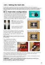
NOTE
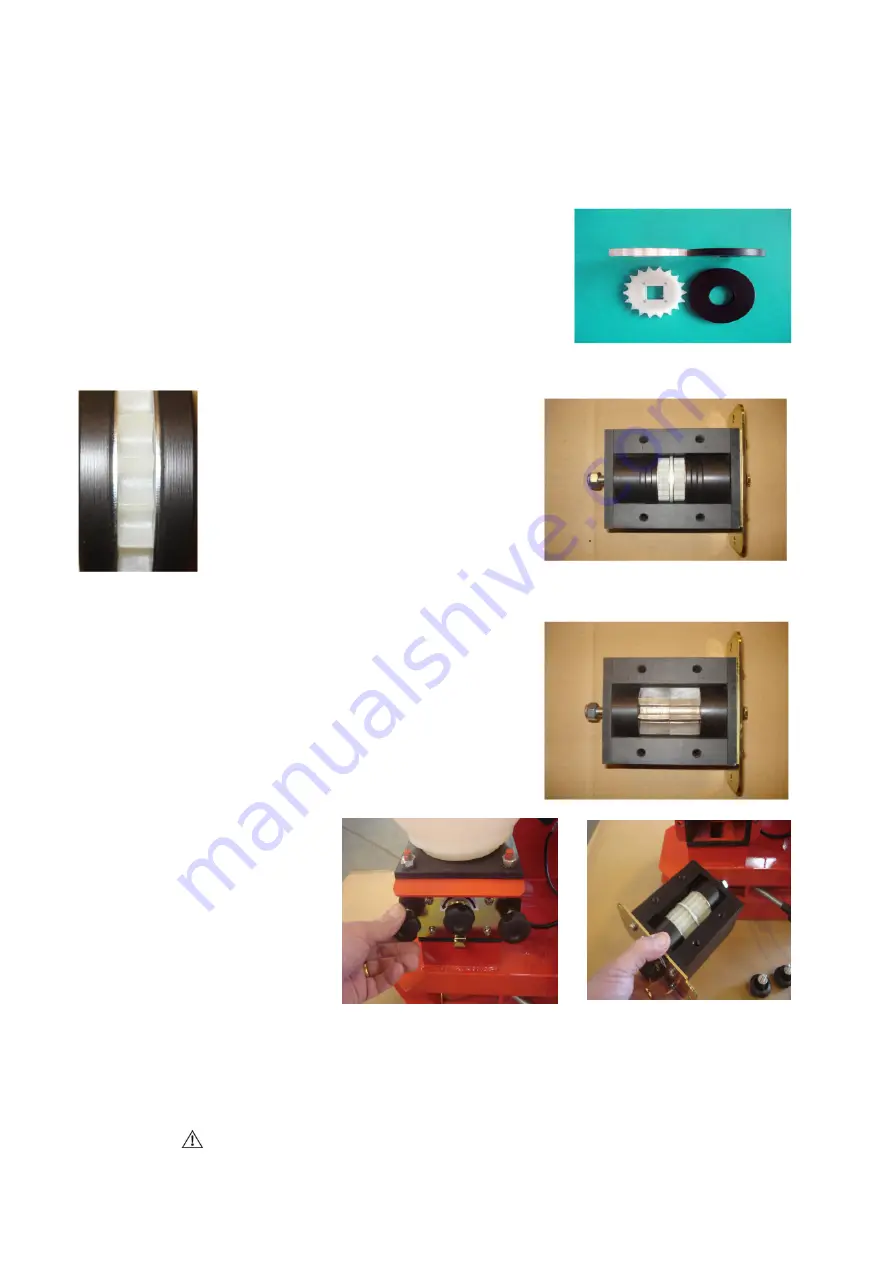
always ensure a stainless
disc is fitted to each side of the set
of 1,2,3,4 or 5 feed rollers used in
each half of the feed block.
They are important and needed to
reduce friction between the feed
rollers and the plastic spacers.
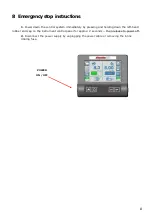
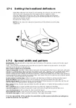
Photo of a feed block assembly with 6
feed rollers and 6 blacking spacers fitted
18-2 Feed roller configuration
For higher outputs or applying large seeds or granules the
machine is also supplied with 2 larger 8 section feed rollers
and spacers to allow 1 or 2 to be fitted as required.
The feed rollers are easily changed by removing the feed
block as follows.
NOTE Empty the hopper completely before removing
the feed block.
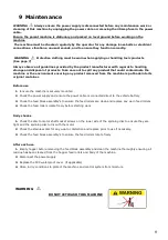
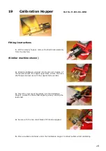
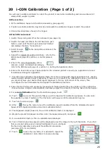
Photo of a feed block assembly with 2
larger 8 section feed rollers fitted
1.
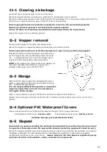
Undo and remove the 2 black
plastic knobs holding the feed block
in place
2.
Slide the complete mechanism out
3.
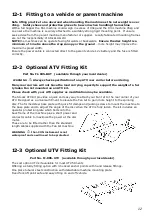
Undo and remove the 4 socket
head screws on the end of the
housing opposite the retaining plate
and remove the end plate
4.
Slide the rollers and spacers off
the shaft, and replace with the
alternative rollers and spacers in the
required combination
5.
Refit the end plates and re-fit the
feed block and black plastic knobs.
The machine is fitted 10 white 5mm polyurethane 18 tooth feed
rollers as standard these have a stainless steel drive disc embed-
ded. Depending on the combination of required seeding rate,
implement width and forward speed 2 to 10 feed rollers can be
fitted with maximum rates achieved by fitting all 10 feed rollers.
The black 5mm wide spacers supplied are the same width as the
white feed rollers and used to replace feed rollers as required

