background image

Description of the demonstration firmware functions

UM0882

8/20

Doc ID 16881 Rev 2

4.1 

Mode “A” - interactive demonstration - color Tetris

Mode 'A' performs a simple interactive demonstration similar to Tetris game. The game 
starts with a green brick moving from the bottom to the top of the LED area. The brick 
position can be controlled by using the right and left buttons. Once the brick reaches the top 
of the LED area of another already settled brick, it stops and turns to blue. A blue brick 
cannot be moved. When a row is full of blue bricks, it disappears and the player scores 
points. The game ends as soon as the blue bricks reach the bottom of the LED area. When 
the game is over, the score is displayed. Pressing the center button starts a new game. The 
knob changes the light brightness of the LEDs.

4.2 

Mode “B” - wave color demonstration

Mode “B” shows different color effects. The effect can also be changed manually by using 
the center button. The knob changes the speed of the effect.

4.3 

Mode “C” - solid color demonstration

Mode “C” allows to display a given color on the LEDs. Pressing the right button changes the 
colors in this order (left button in reverse order): red, green, blue, yellow (red + green), cyan 
(green + blue), magenta (red + blue), white (red + green + blue) and black (all LEDs are off). 
The knob changes the light brightness of the LEDs.

4.4 

Mode “D” - error detection

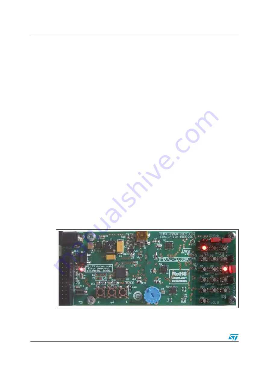
Mode 'D' performs LED error detection, and displays the error. Error detection is performed 
by LED drivers every 2 seconds. If a defective LED is found, it is signalled by switching on 
the corresponding red LED. D1, D2 and D3 green LED open-circuit defect can be simulated 
by removing P20, P21, or P22 jumper. D6, D9 and D12 blue LED short-circuit defect can be 
simulated by closing P1, P2, or P3 jumper. 

Figure 5.

Simulation of LED defect by setting/removing P21 to P2 jumpers

www.BDTIC.com/ST

Summary of Contents for STEVAL-ILL028V1

Page 1: ...L028V1 LED dimmer board This board is based on STP1612PW05 independent PWM LED driver controlled through STM32 microcontroller SPI interface and DMA optional This document explains how to use the boar...

Page 2: ...set USB clock 6 3 4 Jumpers for LED failure simulation 6 4 Description of the demonstration firmware functions 7 4 1 Mode A interactive demonstration color Tetris 8 4 2 Mode B wave color demonstration...

Page 3: ...UM0882 List of tables Doc ID 16881 Rev 2 3 20 List of tables Table 1 Bill of material 17 Table 2 Document revision history 19 www BDTIC com ST...

Page 4: ...y setting removing P21 to P2 jumpers 8 Figure 6 Software Windows application 9 Figure 7 USB host PC detection in progress 10 Figure 8 USB host PC detected 10 Figure 9 USB host PC not found 10 Figure 1...

Page 5: ...The board can be controlled by 3 buttons a knob and a reset back button Test point for each main signal Microcontroller firmware update through JTAG interface Error LED and overtemperature LED for ea...

Page 6: ...onverted to 48 MHz by a PLL The clock is also used to drive USB Since the internal RC oscillator does not allow to achieve the clock stability defined in USB specifications it is recommended not to us...

Page 7: ...e B wave color demonstration Mode C solid color demonstration Mode D error detection demonstration After power up the letter A is displayed blinking An action on a button or on the knob allows to sele...

Page 8: ...olor demonstration Mode B shows different color effects The effect can also be changed manually by using the center button The knob changes the speed of the effect 4 3 Mode C solid color demonstration...

Page 9: ...instead of the on board buttons trigger and visualize the result of the error detection Figure 6 Software Windows application The following steps are required to run the PC demonstration software corr...

Page 10: ...1 Rev 2 Figure 7 USB host PC detection in progress Figure 8 USB host PC detected Figure 9 USB host PC not found 5 Run SWforDimmer exe 6 If the board is not detected automatically click Find board on C...

Page 11: ...ID 16881 Rev 2 11 20 Figure 10 Manual board connection If the board has been found and connected successfully the message Board found on COM4 is displayed in green as depicted on Figure 11 Figure 11...

Page 12: ...rs P20 P21 and P22 are closed and the jumpers P1 P2 and P3 are open the PC demonstration software will not report any LED defect after clicking Perform error detection See Figure 12 2 Moving the jumpe...

Page 13: ...7 8 9 10 11 12 13 14 15 16 17 18 19 20 CN1 GM MLW20G 3V3 JTRST JTDI JTMS JTCK JRTCK JTDO JRST DBGRQ DBGACK R23 10 K R22 10 K 3 3 V R20 10 K C10 100 nF S1 LEFT C12 100 nF S3 RIGHT C11 100 nF S2 CENTER...

Page 14: ...PA7 MOSI SPI1 17 VSS_1 23 VDD_1 24 STM32 U3 STM32F103Cx C6T6 3 3 V 3 3 V 3 3 V 3 3 V SDI SDO CLK USBDP USBDN VIN_ A 1 EN 2 FB 3 SW 7 SYNC 5 AGND 4 PGND 8 VIN_SW 6 ST1S10 9 U4 ST1S10 ceramic 25 V 35 V...

Page 15: ...RGB LED A A CR CR CG CG CB CB D14 RGB LED A A CR CR CG CG CB CB D2 RGB LED A A CR CR CG CG CB CB D5 RGB LED A A CR CR CG CG CB CB D8 RGB LED A A CR CR CG CG CB CB D12 RGB LED A A CR CR CG CG CB CB D1...

Page 16: ...OUT13 16 OUT14 17 OUT15 18 20 19 OUT12 15 21 22 STP1612 0 QFN24 U7 STP1612PW05 D11 D21 D31 D41 D51 D61 D71 D81 D141 D151 D161 SDI SDOI1 LE CLK R5 68 k 3 3 V 3 3 V 3 3 V C9 100 nF 3 3 V PWCLK GND 10 SD...

Page 17: ...or Input power 4 4V 36V DC10B D1 D16 RGB LED OSRAM LATB_T686 TOPLED D17 Diode bridge Full wave diode bridge GMBridgeBig D18 Protection diode SM6T18AC SMA DDD1 ST_LOGO Label ST LOGO DDD2 ROH1 Label ROH...

Page 18: ...ble S4 RESET EXIT Small button Button_DT2112C U1 STP1612PW05 STP1612PW05 QFN24 QFN24_STP1612PW05 U2 STP1612PW05 STP1612PW05 QFN24 QFN24_STP1612PW05 U3 STM32F103C6T6 Microcontroller STM32 TQFP48 U4 ST1...

Page 19: ...on history Doc ID 16881 Rev 2 19 20 8 Revision history Table 2 Document revision history Date Revision Changes 12 Mar 2010 1 Initial release 08 Jul 2010 2 Updated Section 2 Board function overview www...

Page 20: ...OF MERCHANTABILITY FITNESS FOR A PARTICULAR PURPOSE AND THEIR EQUIVALENTS UNDER THE LAWS OF ANY JURISDICTION OR INFRINGEMENT OF ANY PATENT COPYRIGHT OR OTHER INTELLECTUAL PROPERTY RIGHT UNLESS EXPRES...

Reviews: