Instruction Manual Notice d’emploi
STIH)
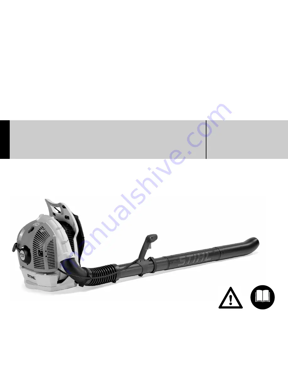
STIHL BR 500, 550, 600
Page 1: ...Instruction Manual Notice d emploi STIH STIHL BR 500 550 600 ...
Page 2: ...ength adjustable blowing attachment 34 Specifications 36 Special Accessories 37 Maintenance and Repairs 37 STIHL Limited Emission Control Warranty Statement 38 Allow only persons who understand this Manual to operate your blower To receive maximum performance and satisfaction from your STIHL blower it is important that you read and understand the maintenance and safety precautions starting on page...
Page 3: ...ere there is a risk of damaging the machine or its individual components Note or hint which is not essential for using the machine but may improve the operator s under standing of the situation and result in better use of the machine Note or hint on correct procedure in order to avoid damage to the environment Equipment and features This instruction manual may refer to several models with differen...
Page 4: ...w to operate your blower Observe all applicable local safety regulations standards and ordinances Warning Minors should never be allowed to use a blower Bystanders especially children and animals should not be allowed in the area where a machine is in use Never let the unit run unattended Most of these safety precautions and warnings apply to the use of all STIHL blowers Different models may have ...
Page 5: ...footing is most important Wear sturdy shoes with nonslip soles Warning To reduce the risk of injury associated with the inhalation of dust use an appropriate dust respirator for the material being blown Warning Use of this product can generate dust mists and fumes containing chemicals known to cause respiratory disease cancer birth defects or other reproduc tive harm If you are unfamiliar with the...
Page 6: ...e a blower unless wearing goggles or properly fitted safety glasses with adequate top and side protection which comply with ANSI Z 87 1 or your applicable national standard Fellow workers must also wear personal protective equipment Warning Blower noise may damage your hearing Wear sound barriers ear plugs or ear mufflers to help protect your hearing Continual and regular users should have their h...
Page 7: ...t down When transporting your unit in a vehicle properly secure it to prevent turnover fuel spillage and damage to the machine Adjust carrying harness to suit your size before starting work Warning Before starting work always inspect the rubber buffers which connect the engine to the pack frame If the buffers are torn or damaged they should be replaced by your STIHL dealer Failure of one or more b...
Page 8: ... raise the grip on the top of the cap until it is upright at a 90 angle Insert the cap in the fuel tank opening with the triangular marks on the grip of the cap and on the fuel tank opening lining up Using the grip turn the cap firmly clockwise as far as it will go approx a quarter turn Fold the grip flush with the top of the cap If the grip does not lie completely flush with the cap and the deten...
Page 9: ...t from thrown objects or from contact with fumes the engine should be kept at idle speed during this brief period and your assistant should not stand in the area of the outlet nozzle or exhaust Otherwise the unit should be started and operated without assistance Warning To reduce the risk of fire or burn injury let the unit cool down before refueling your blower after use Warning Never disassemble...
Page 10: ...sk of personal injury do not direct air blast towards bystanders since the high pressure of the air flow could injure eyes and could blow small objects at great speed Warning Always shut off the engine before cleaning or servicing the unit or replacing parts Warning The blower fan between the air intake and output openings rotates whenever the engine is running Never insert any foreign object into...
Page 11: ...an work close to the ground Do not direct debris at people children pets at open windows or freshly washed cars Blow debris safely away After using blowers CLEAN UP Dispose of debris in trash receptacles Do not blow debris onto neighboring properties Recommended working techniques to minimize noise Operate power equipment only at reasonable hours not early in the morning late at night or during th...
Page 12: ... screws except the carburetor adjustment screws after each use Warning A worn or damaged muffler is a fire hazard and may cause loss of hearing Check to see that the muffler is in good condition The blower must not be opera ted if the muffler is not functioning pro perly or has been removed Remember that the risk of forest fires is greater in hot weather Use the spark arresting muffler supplied wi...
Page 13: ...cing left onto the blower tube shoulder 2 Pass the discharge wire 1 through the hose clamp 7 without retainer for throttle cable screw recess facing you Pass the discharge wire 1 through the pleated hose 7 Push the blower tube 2 into the pleated hose 7 Secure the hose clamp 6 with screw 8 Pass the discharge wire 1 through the pleated hose 7 and hose clamp 9 with retainer for throttle cable screw r...
Page 14: ...ght depending on market onto the blower tube 2 and engage it on the lug 14 Operate the machine only with a properly fitted discharge wire The hook on the discharge wire must be attached to the eye arrow The sleeve on the discharge wire must be clipped to the retainer arrow The discharge wire must engage the groove arrow The discharge wire must project at least 1 cm 452BA060 KN 7 9 12 11 452BA018 S...
Page 15: ...andle 1 along the tube to the most comfortable position Tighten down the screw 3 firmly Clip throttle cable 4 with sleeve 5 to retainer 6 Disassembling the Blower Tubes and Control Handle Reverse the assembly procedure Take care not to damage the discharge wire during disassembly Rotate the nozzle and blower tubes to disengage them from the lugs and then remove them ...
Page 16: ...ment Machines with a length adjustable blowing attachment have no discharge wire Any buildup of static electricity is dissipated via the conductive control handle See Guide to Using the Manual Mounting the Blower Tubes BR 500 Push blower tube 1 onto blower tube 2 and engage it in one of the slots 3 BR 550 600 Push blower tube 1 onto blower tube 2 and engage it in one of the slots 3 Assembling the ...
Page 17: ...ecure the hose clamp 5 with screw 7 8 Line up the hose clamp 8 with retainer for throttle cable screw recess and retainer facing you Push the pleated hose 6 with hose clamp 8 over the elbow 9 Tighten down the screw 10 firmly Push the nozzle 11 curved or straight depending on market onto the blower tube 2 and engage it on the lug 12 452BA076 KN 2 4 452BA077 KN 5 6 5 452BA078 KN 2 7 452BA079 KN 8 45...
Page 18: ...ove the control handle 1 along the tube to the most comfortable position Tighten down the screw 3 firmly Clip throttle cable 4 with sleeve 5 to retainer 6 Fitting the Transport Aid When storing or transporting the machine Secure the velcro strip to the blower tube pull the flap through the buckle Attach blower tube to handle opening in the backplate ...
Page 19: ...ger to the full throttle position as far as stop Turn the screw in the throttle trigger slowly clockwise until you feel initial resistance Adjust the harness straps so that the backplate is held firmly and comfortably against your back A Adjust height B Adjust angle Tightening the harness straps Pull the ends of the straps downward Loosening the harness straps Lift the tabs of the two sliding adju...
Page 20: ...turn increases the risk of the piston seizure and damage to the engine The chemical composition of the fuel is also important Some fuel additives not only detrimentally affect elastomers carburetor diaphragms oil seals fuel lines etc but magnesium castings as well This could cause running problems or even damage the engine For this reason it is essential that you use only high quality fuels Fuels ...
Page 21: ...dd gasoline Examples Dispose of empty mixing oil canisters only at authorized disposal locations Before fueling clean the filler cap and the area around it to ensure that no dirt falls into the tank Position the machine so that the filler cap facings up In order to reduce the risk of burns or other personal injury from escaping gas vapor and fumes remove the fuel filler cap carefully so as to allo...
Page 22: ...upted the engine stops Setting lever does not remain in this position it springs back Run position Engine runs or can be started Throttle trigger can be operated normally C Lock position The throttle trigger can be locked in three positions 1 3 throttle 2 3 throttle and full throttle To disengage the lock move the setting lever back to the normal run position Starting the Engine Start the machine ...
Page 23: ... footing Hold the machine firmly with your left hand on the housing and put one foot against the base to prevent it slipping Pull the starter grip slowly with your right hand until you feel it engage and then give it a brisk strong pull Do not pull out the starter rope all the way it might otherwise break Do not let the starter grip snap back Guide it slowly back into the housing so that the start...
Page 24: ... moves automatically to the run position or Move the choke knob to the run position At very low outside temperatures Open the throttle slightly warm up the engine for a short period If the engine does not start If you did not turn the choke knob to n quickly enough after the engine began to fire the combustion chamber is flooded Turn the choke knob to n Move the setting lever 1 to C Engage the thr...
Page 25: ...opping the Engine Move the setting lever 1 to 0 the engine stops the setting lever springs back when it is released Dirty air filters reduce engine power increase fuel consumption and make starting more difficult If there is a noticeable loss of engine power Turn the choke knob to l Take out the screws 1 Remove the filter cover 2 452BA026 KN 1 Replacing the Air Filter ...
Page 26: ...n of the fundamental engine parameters and components e g carburation ignition timing and valve or port timing without the addition of any major hardware The carburetor comes from the factory with a standard setting This setting provides an optimum fuel air mixture under most operating conditions With this carburetor it is only possible to make corrections to the high speed and low speed screws wi...
Page 27: ... spite of correction to setting of LA screw poor acceleration Idle setting too lean Turn low speed screw L counterclockwise no further than stop until the engine runs and accelerates smoothly but no further than stop Erratic idling behavior Idle setting too rich Turn low speed screw L clockwise no further than stop until the engine runs and accelerates smoothly It is usually necessary to change th...
Page 28: ...ype spark plugs of the approved range Rectify problems which have caused fouling of spark plug Too much oil in fuel mix Dirty air filter Unfavorable running conditions e g operating at part load Fit a new spark plug after approx 100 operating hours or earlier if the electrodes are badly eroded To reduce the risk of fire and burn injury use only spark plugs authorized by STIHL Always press spark pl...
Page 29: ...ting screen If screen is damaged or heavily carbonized fit a new one Refit the spark arresting screen Fit the scoop Replacing the starter rope Take out the screws 1 Remove the starter cover 2 Use a screwdriver or suitable pliers to ease the spring clip 3 off the starter post The rewind spring may pop out and uncoil take care to avoid injury Carefully remove the rope rotor with washer 4 and pawls 5...
Page 30: ...rough the top of the rope bushing 6 and the rotor 7 and secure it with a simple overhand knot Lubricate the rope rotor bore with non resinous oil Push the rope rotor onto the starter post 8 and turn it back and forth to engage the rewind spring s anchor loop Fit the pawls 5 in the rotor Fit the washer 4 on the starter post Use a screwdriver or suitable pliers to install the spring clip 3 on the st...
Page 31: ...nd could fly apart when you take them out of the housing To reduce risk of injury wear eye and face protection and work gloves Remove the rope rotor Use a screwdriver to carefully remove the spring housing 1 and remaining parts of the spring Lubricate the new spring with a few drops of non resinous oil Place the new spring with spring housing in the starter cover Fit the rope rope tension the rewi...
Page 32: ...Replace x x Filter in fuel tank Have checked by dealer1 x Have filter replaced by dealer1 x x Fuel tank Clean x Carburetor Check idle setting x x Readjust idle x Spark plug Readjust electrode gap x Replace after 100 hours of operation Cooling air intakes Clean x Valve clearance Check adjust if necessary after 139 hours of operation x Combustion chamber Decoke after 139 hours of operation then ever...
Page 33: ...d hose 10 Harness 11 Back plate 12 Intake screen 13 Air Filter Housing 14 Fuel filler cap 15 Spark plug boot 16 Muffler with spark arresting screen 17 Carburetor adjusting screws 18 Choke knob 19 Fuel pump 20 Starter grip 21 Fuel tank 22 Conductor wire BR 500 23 Conductor wire BR 550 600 Serial number see Guide to Using this Manual Parts and Controls with non adjustable blowing attachment 452BA070...
Page 34: ...he back of the user 12 Intake Screen Helps prevent leaves entering intake 13 Air Filter Housing Covers the air filter element 14 Fuel Filler Cap For closing the fuel tank 15 Spark Plug Boot Connects the spark plug to the ignition wire 16 Muffler with spark arresting screen Attenuates exhaust noises and diverts exhaust gases away from operator The spark arresting screen is designed to reduce the ri...
Page 35: ... 9 Pleated hose 10 Harness 11 Back plate 12 Intake screen 13 Air Filter Housing 14 Fuel filler cap 15 Spark plug boot 16 Muffler with spark arresting screen 17 Carburetor adjusting screws 18 Choke knob 19 Fuel pump 20 Starter grip 21 Fuel tank Serial number see Guide to Using this Manual Parts and Controls with length adjustable blowing attachment 14 12 13 452BA082 KN 1 2 3 4 5 6 7 8 9 10 11 ...
Page 36: ...n the desired direction 10 Harness For carrying the unit 11 Backplate Helps protect the back of the user 12 Intake Screen Helps prevent leaves entering intake 13 Air Filter Housing Covers the air filter element 14 Fuel Filler Cap For closing the fuel tank 15 Spark Plug Boot Connects the spark plug to the ignition wire 16 Muffler with spark arresting screen Attenuates exhaust noises and diverts exh...
Page 37: ...k ignition system meets all requirements of the Canadian Interference Causing Equipment Regulations ICES 002 Fuel System Rewind starter Starter rope dia 3 5 mm x 960 mm Weights Maximum air throughput Air velocity STIHL 4 MIX Motor Displacement 64 8 cm3 Bore 50 mm Stroke 33 mm Idle speed 2 500 rpm Specifications Type Electronic magneto ignition Spark plug suppressed NGK CMR 6 H Electrode gap 0 7 mm...
Page 38: ...bed in this manual Other repair work may be performed only by authorized STIHL service shops Warranty claims following repairs can be accepted only if the repair has been performed by an authorized STIHL servicing dealer using original STIHL replacement parts Original STlHL parts can be identified by the STlHL part number the STIHl logo and in some cases by the STlHL parts symbol This symbol may a...
Page 39: ...our small off road equipment engine but STIHL Limited cannot deny warranty solely for the lack of receipts or for your failure to ensure the performance of all scheduled maintenance Any replacement part or service that is equivalent in performance and durability may be used in non warranty mainten ance or repairs and shall not reduce the warranty obligations of the engine manufacturer As the small...
Page 40: ...ive Any manufacturer approved or equivalent replacement part may be used for any warranty maintenance or repairs on emission related parts and must be provided without charge to the owner STIHL Limited is liable for damages to other engine components caused by the failure of a warranted part still under warranty The following list specifically defines the emission related warranted parts Carbureto...