STIEBEL ELTRON wpf 20, Operation And Installation
The "STIEBEL ELTRON wpf 20" Operation and Installation manual is available for free download at manualshive.com. This comprehensive manual provides step-by-step instructions and essential information for setting up and using the product. Ensure a smooth user experience by accessing the manual effortlessly from our website.
Share
Download


Reviews:
No comments
Related manuals for wpf 20

GP
Brand: EBARA Pages: 164

Panther SE 06
Brand: Frico Pages: 28

LBT Series
Brand: Lochinvar Pages: 16

F2015
Brand: Nibe Pages: 44

Drain TM 32
Brand: Wilo Pages: 80

BLACKLIGHT 7815
Brand: MO-EL Pages: 12

Smartmax Series
Brand: ubbink Pages: 29

LARIUS SIRIO 60:1
Brand: Samoa Pages: 46

EA120
Brand: Unitary products group Pages: 24

Claris home
Brand: salmson Pages: 36

SH261
Brand: Bard Pages: 25

ELSH12P30E
Brand: Daikin Pages: 52

5FES 50HZ
Brand: foras Pages: 8

HPS4HDX
Brand: Pentair Hydromatic Pages: 20

General Pump EV Series
Brand: Interpump Pages: 19
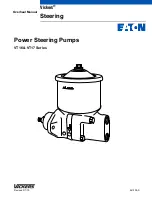
Vickers VT16
Brand: Eaton Pages: 11

AGE-1-3
Brand: Juwent Pages: 15

BMV Series
Brand: Barmesa Pumps Pages: 22


