6
1.6 Transport and positioning
1.6.1 Transport
To protect the equipment against damage,
it must be transported vertically inside its
dedicated packaging. Storage and transport at
temperatures below – 20 °C and in excess of +
50 °C are not permissible.
1.6.2 Positioning
1. Remove the equipment from its pallet and
position it where required.
2. Remove the eight screws from the
equipment plinth (Fig. 5), and set down the
casing onto the floor.
!
The casing must stand on the floor
free from the refrigeration unit.
That means, the eight plinth screws must
not be refitted.
!
Checking installation conditions. The
heat pump WPF...M(S) is designed
for installation in interiors, except in wet
areas.
The room where the WPF...M(S) is to be
installed must also meet the following
conditions:
z
No risk from frost.
z
Load-bearing floor (weight of the WPF..M(S)
approx. 145 kg).
z
Horizontal, level and solid floor, as the
equipment feet on the heat pump are non-
adjustable.
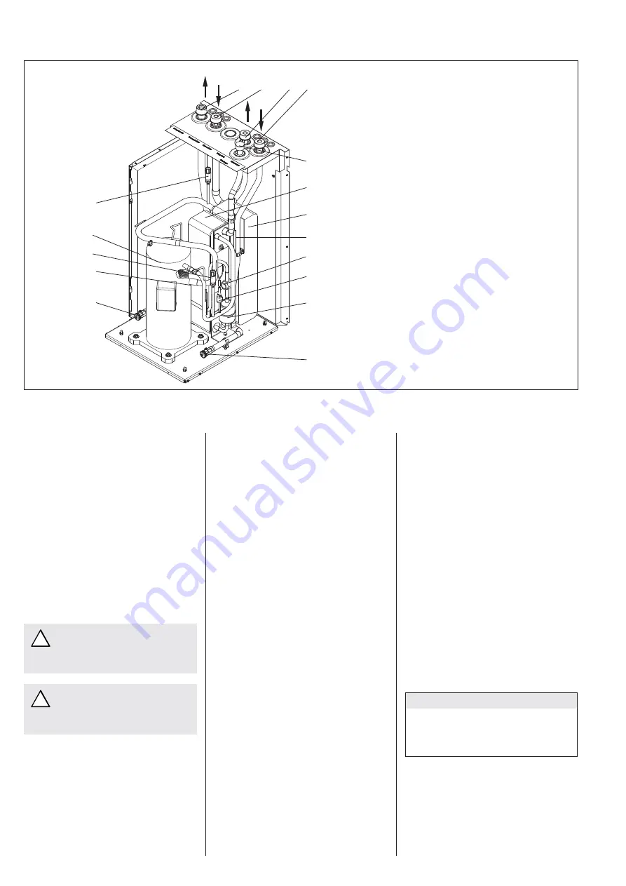
1 Brine
outlet
2 Brine
inlet
3 Heating
flow
4 Heating
return
5
Safety assembly connection
(included in the pack)
6 Condenser
7 Evaporator
8
Sensor well for return sensor
9 Sight
glass
10
High pressure limiter
11
Filter dryer
12
Fill & drain valve (heating)
13
Fill & drain valve (brine)
14
Expansion valve
15
Compressor
16
Low pressure limiterr (only for mono phase)
16
ND-sensor (only for triple phase)
17
HD-sensorr (only for triple phase)
WPF 7 MS
WPF 10 M(S)
WPF 13 M
WPF 16 M
Fig. 3
z
For a quiet heat pump operation on floating
screeds, remove the screed and the anti-
vibration insulation around the installation
location of the heat pump
(Fig. 8).
z
The room must not be subject to a risk
of explosions arising from dust, gases or
vapours.
z
The floor area of the installation room must
be at least 3 m², and the room must provide
a volume of 6 m³ (minimum).
z
When installing the WPF ...M in a boiler
room together with other heating
equipment ensure, that the operation
of other heating equipment will not be
impaired.
1.6.3 Installation of the heat source system for
the WPF ...M(S) with brine as heat source
Design the heat source system for the brine/
water heat pump in accordance with the
Stiebel Eltron technical guides.
Permitted brine:
– Ethylene
glycol
– Propylene
glycol
– Concentrated heat transfer medium
Part no: 161696
– Heat transfer medium (ready-mixed)
Part no: 185472
When using ready-mixed heat transfer
medium (part no. 185472), never seal the heat
source system with hemp.
1.6.3.1 Circulation pump and required flow
rate
Use a circulation pump with compound-filled
windings to supply the brine, to prevent an
earth short circuit through condensation in
the electrical part of the pump (cold water
version).
Size the circulation pump in accordance with
the system-specific conditions, i.e. observe
the nominal flow rate and pressure drop
(see 1.5 “Specification”, page 3).
An adequate flow rate must be safeguarded at
every possible brine temperature, i.e.:
– Nominal flow rate at brine temperature
0 °C with a tolerance of +10 %.
1.6.3.2 Connection and filling with brine
Prior to connecting the heat pump, check the
heat source circuit for possible leaks, and
flush thoroughly. Calculate the volume of
the heat source circuit. You can obtain the
brine volume inside the heat pump from the
following table.
Heat pump
Brine volume
WPF 7(S)
6.45 l
WPF 10(S) / 13 M
7.06 l
WPF 16 M
7.73 l
The overall volume equals that of the required
volume of brine, which should be mixed from
33 % vol. undiluted ethylene glycol and 67 %
vol. water.
Mixing ratio:
C26_03_01_0208
Equipment layout
1
2
3
4
5
6
7
9
12
8
10
13
16
15
14
11
17


